
Device and method for detecting uniform distribution positions of blade-shaped holes in thin-wall fan-shaped section

A detection device and leaf-shaped hole technology, applied in the direction of measuring devices, mechanical measuring devices, mechanical devices, etc., to achieve the effect of novel structure, ensuring assembly requirements, and convenient operation

Pending Publication Date: 2022-01-07
AECC AVIATION POWER CO LTD
View PDF0 Cites 0 Cited by
  • Summary
  • Abstract
  • Description
  • Claims
  • Application Information

AI Technical Summary

Problems solved by technology

[0003] Aiming at the problems existing in the prior art, the present invention provides a detection device and a detection method for the evenly distributed position of the airfoil holes in the thin-walled sector, which can quickly and accurately realize the measurement of the uniformly distributed position of the airfoil holes in the thin-walled sector to solve the problem of Thin-wall fan-shaped airfoil has poor rigidity, large deformation, and difficult to detect measurement problems

Method used


Image

  • Device and method for detecting uniform distribution positions of blade-shaped holes in thin-wall fan-shaped section
  • Device and method for detecting uniform distribution positions of blade-shaped holes in thin-wall fan-shaped section
  • Device and method for detecting uniform distribution positions of blade-shaped holes in thin-wall fan-shaped section

Examples


Embodiment

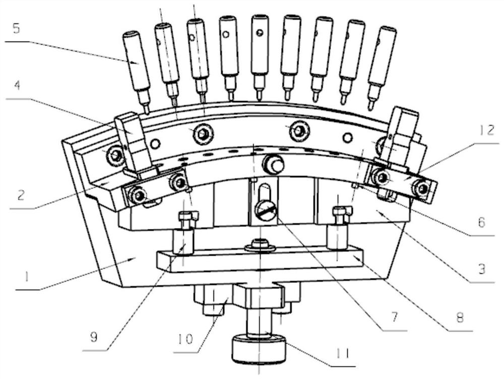
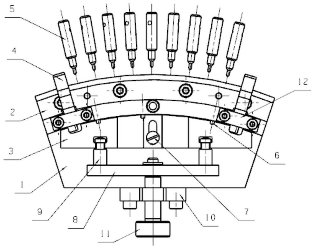
[0048] The inside of the arc-shaped positioning block 2 in the detection device is positioned in positioning the outer tapered surface of the part to be tested, and the end surface is positioned as the upper surface of the base 1, since the wall thickness of the part to be tested is too thin, the rigidity difference is large, and the end surface position is only width. 0.5mum loop must be designed with a limit device in both axial and radially direction to ensure that the thin-walled secting segment is accurate and reliable. The curved positioning block 2 is designed with a circular hole of 3 out of 3, and the positioning pin 6 is mounted in this circular hole, three positioning pin 6 minimum bus wires to the size of the upper surface of the base 1, axially size The maximum design (that is, the size of the lowest busbar of the positioning pin 6 to the upper end surface of the base 1 is equal to the maximum value of the axial dimension of the part to be tested), achieving an axial ...


PUM


Abstract

The invention discloses a device and method for detecting the uniform distribution positions of blade-shaped holes in a thin-wall fan-shaped section. The inner conical surface of an arc-shaped positioning block can be attached to the outer conical surface of a to-be-detected part, and the positions, close to the two ends, of the arc-shaped positioning block are provided with through grooves which are consistent with the theoretical uniform distribution positions of blade-shaped holes in the two ends of a to-be-measured part, a measuring block is arranged in each through groove in a sliding manner, the measuring end of each measuring block is the same as the theoretical shape of the blade-shaped holes of the to-be-measured part, and the size of the measuring end is equal to the result of the difference of the minimum entity of the blade-shaped holes and the uniform distribution position degree; guide holes consistent with the theoretical uniform distribution positions of the remaining blade-shaped holes of the to-be-measured part are formed in the arc-shaped positioning block and located between the two through grooves, a measuring pin is arranged in each guide hole in a sliding mode, and the diameter of the measuring end of each measuring pin is obtained by subtracting the uniform distribution position degree from the diameter of thesmallest blade-shaped hole inscribed circle in the corresponding position; and a movable pressing block is slidably arranged on the upper end face of a base. According to the device and method of the invention, the measurement of the uniform distribution positions of the blade-shaped holes of the thin-wall fan-shaped section can be rapidly and accurately realized.

Description

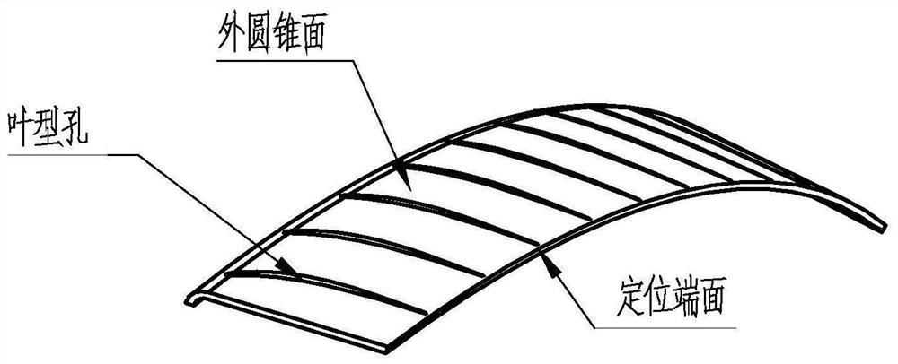
Technical field [0001] The present invention belongs to the technical field of air engine thin-walled sector segment detection, and in particular to a thin-walled segment leaf-type hole homogeneous position detecting device and a detection method. Background technique [0002] The thin-walled seaflic leaf plate belongs to the sheet metal punching, such as figure 1 As shown, the wall thickness is only 0.5 mm, and there is a leaf type hole for mounting the blade on its circumference. The leaf type hole is multi-use laser punching method, and the hiking hole of the leaf hole needs to be detected, due to the thin wall The impeller plate rigidity is large, deformed, and the three coordinates are used, and the measurement error is large and the efficiency is low, and the design of the designed dedicated detection device is required to perform limit measurement. Inventive content [0003] For the problems present in the prior art, the present invention provides a thin-walled segment le...

Claims


Application Information

Patent Timeline
Patent Type & Authority Applications(China)
IPC IPC(8): G01B5/00
CPCG01B5/003
Inventor 牛阿妮张玉宝王荣姚妮高锋利党小莉罗俊党红武
Owner AECC AVIATION POWER CO LTD
Learn More