Detection device and method for measuring movement of turbine flowmeter

A technology of turbine flowmeter and detection device, which is applied to devices using optical methods, testing/calibrating volume flow, etc., can solve the problems of increasing the manufacturing cost of flowmeters, high requirements, and time-consuming, so as to ensure reliability and overall Efficiency, Accurate Metrology Performance, Reduced Manufacturing Costs

Pending Publication Date: 2022-01-07
ZHEJIANG CANGNAN INSTR GRP CO LTD
View PDF0 Cites 0 Cited by
  • Summary
  • Abstract
  • Description
  • Claims
  • Application Information

AI Technical Summary

Problems solved by technology

[0003] At present, in the production of this flowmeter, the domestic manufacturers mainly rely on the experience of the production operators to inspect the measuring core. After they think it is basically normal, they will carry out the general assembly of the whole machine, and the subsequent standard device verification will finally determine the whole machine. However, this method seems to reduce the production process, but it has very high requirements for the technical experience of the production staff and the quality inspection of the corresponding internal parts. If the flowmeter is found to be unqualified, it must be returned to the production assembly line for inspection It is disassembled for detailed inspection, and the airtightness test and verification of the whole machine need to be done again after repairing. This process is very time-consuming and inefficient for production, and increases the manufacturing cost of the flowmeter as a whole.

Method used


Image

  • Detection device and method for measuring movement of turbine flowmeter
  • Detection device and method for measuring movement of turbine flowmeter
  • Detection device and method for measuring movement of turbine flowmeter

Examples


Embodiment Construction

[0028] The specific embodiment of the present invention is described in detail below in conjunction with accompanying drawing:

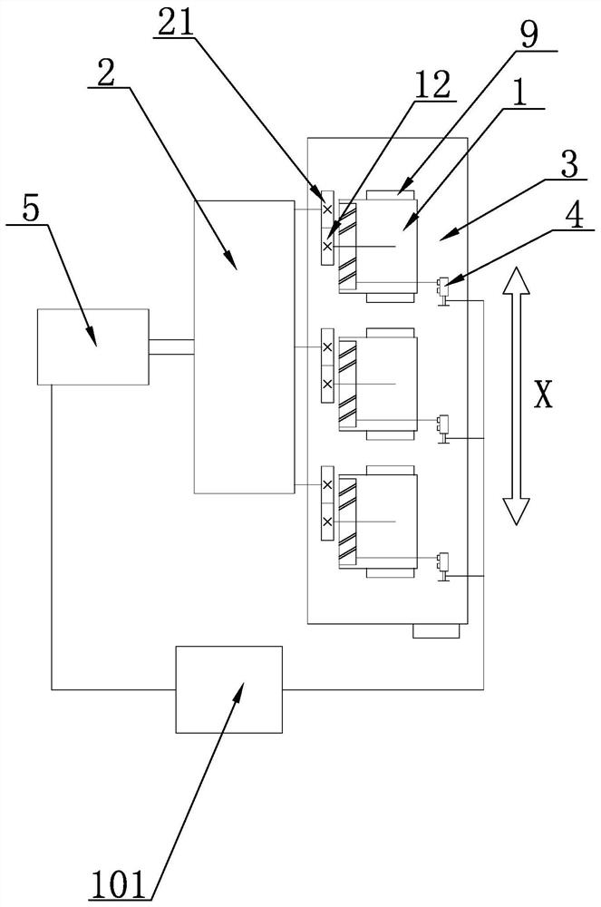
[0029] Mounting table 3 can be along the figure 1 The middle arrow reciprocates in the X direction. The specific installation method can be to use guide rails to slide or use other methods to guide the movement. The specific installation belongs to the common knowledge of those skilled in the art. This article will not introduce it in detail. The detecting movement is the measuring movement of the turbine flowmeter.

[0030] The disclosure of the present invention relates to a detection device for a measuring core of a turbine flowmeter. In an implementation case of the present invention, it includes:

[0031] The transmission device 2 is used to drive the transmission gear 12 to rotate. The output end of the transmission device 2 is provided with a drive gear 21, and the drive gear 21 cooperates with the output end of the transmission device 2;

...


PUM


Abstract

The invention discloses a detection device for a measuring movement of a turbine flowmeter. A transmission device is driven to rotate by a speed regulating motor, the transmission device drives a driving gear to rotate, and a transmission gear and the driving gear can be meshed by a sliding mounting table, so that an impeller is driven to rotate. A laser sensor collects the high-frequency pulse number, and transmits the collected high-frequency pulse number to a signal processor, the signal processor obtains a flow value through calculation and displays the flow value, the rotating speed of the output end of a speed regulating motor is controlled through a speed regulating switch, so that the flow value reaches a specified value, and a mounting table is driven to slide to separate a driving gear from a transmission gear; and an impeller rotation timer is used for recording the time from free rotation to rotation stop of the impeller, so that the performance of the detected movement is judged, the requirement for technical experience of workers is low, metering performance detection can be carried out on the detected movement before the turbine flowmeter is assembled completely, and the reliability and the overall efficiency of production and maintenance work are ensured.

Description

technical field [0001] The invention relates to the technical field of turbine flowmeter detection, in particular to a detection device and method for a turbine flowmeter measuring core. Background technique [0002] A gas turbine flowmeter is generally composed of a housing, a meter head, a rectifier, a measuring core, a fuel pump, and some auxiliary structures. The measuring core includes impellers, main shafts, bearings, supports, transmission gears, sleeves and other important parts. , is the key component of the flowmeter to realize the accurate measurement function. [0003] At present, in the production of this flowmeter, the domestic manufacturers mainly rely on the experience of the production operators to inspect the measuring core. After they think it is basically normal, they will carry out the general assembly of the whole machine, and the subsequent standard device verification will finally determine the whole machine. However, this method seems to reduce the ...

Claims


Application Information

Patent Timeline
Patent Type & Authority Applications(China)
IPC IPC(8): G01F25/10G01P3/36
CPCG01P3/36
Inventor 肖云巩黄智慧杨龙吴克宏
Owner ZHEJIANG CANGNAN INSTR GRP CO LTD
Why Eureka
Try Eureka