
Optical density testing system and optical density tester

A test system and optical density technology, applied in photometry, optical radiation measurement, instruments, etc., can solve the problems of inability to accurately simulate the test light source, troublesome operation, etc., and achieve the effects of low loss, improved accuracy, and convenient use.

Pending Publication Date: 2022-01-07
TRIPLE WIN TECHSHENZHEN CO LTD
View PDF8 Cites 0 Cited by
  • Summary
  • Abstract
  • Description
  • Claims
  • Application Information

AI Technical Summary

Problems solved by technology

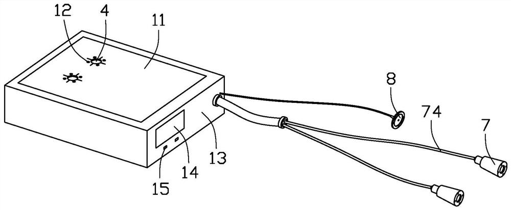
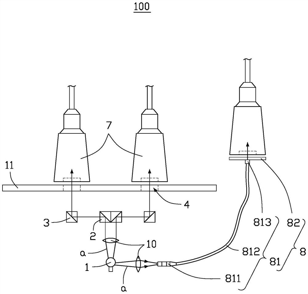
[0004] The traditional optical density tester usually has a single light source plus a single probe, which can only measure one point at a time; and can only test 300-800nm ​​white light, which cannot accurately simulate the test light source; for different sizes of test points, different apertures are required. The light bar, and the light bar with different apertures needs to be replaced manually, which is troublesome to operate

Method used


Image

  • Optical density testing system and optical density tester
  • Optical density testing system and optical density tester
  • Optical density testing system and optical density tester

Examples


Embodiment Construction

[0043] The following will clearly and completely describe the technical solutions in the embodiments of the present invention with reference to the accompanying drawings in the embodiments of the present invention. Obviously, the described embodiments are only some, not all, embodiments of the present invention. Based on the embodiments of the present invention, all other embodiments obtained by persons of ordinary skill in the art without making creative efforts belong to the protection scope of the present invention.

[0044] It should be noted that when a component is said to be "fixed" to another component, it can be directly on the other component or there can also be an intervening component. When a component is said to be "connected" to another component, it may be directly connected to the other component or there may be intervening components at the same time. When a component is said to be "set on" another component, it may be set directly on the other component or t...


PUM


Abstract

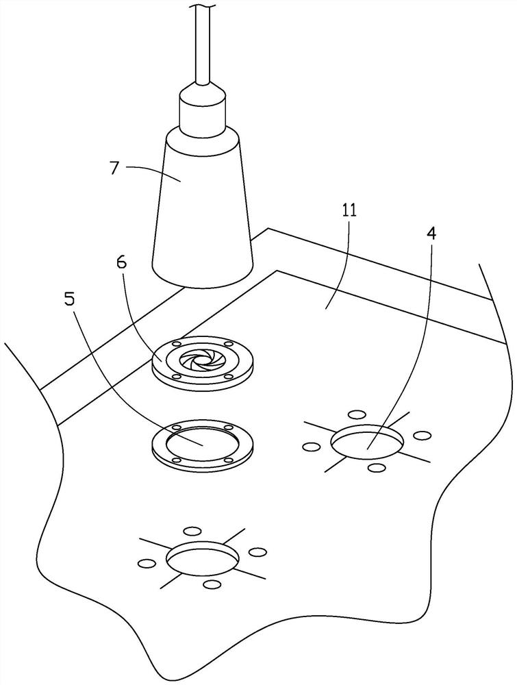
The invention discloses an optical density testing system and an optical density tester. The optical density testing system comprises a light source, a first light splitting device, at least two second light splitting devices, a first light through hole, a first filtering device, a first diaphragm and at least two light receiving devices, and a product to be tested is placed between the first diaphragm and the light receiving devices; the light source is used for emitting light; the first light splitting device is used for splitting light into at least two paths and transmitting the at least two paths of light to the corresponding second light splitting devices respectively; the second light splitting device is used for irradiating the light onto the to-be-tested product through the first light through hole, the first filtering device and the first diaphragm; and the light receiving devices are used for receiving transmission light passing through the product to be tested. In addition, the invention also provides an optical density tester.

Description

technical field [0001] The invention relates to the field of optical density testing equipment, in particular to an optical density testing system and an optical density testing instrument. Background technique [0002] Optical density (OD) is a very important parameter in the packaging and printing industry. Larger printing factories will measure the optical density of printed products to ensure the color quality of printed products. [0003] Optical density indicates the light-shielding ability of the material. Optical density is the logarithm of the ratio of incident light to transmitted light or the logarithm of the reciprocal of light transmittance, that is, OD=lg(incident light / transmitted light)=lg(1 / light transmittance ). Therefore, the optical density can be calculated by measuring the light intensity of the parallel light and the light intensity of the parallel light passing through the object to be tested. [0004] The traditional optical density tester usually ...

Claims


Application Information

Patent Timeline
Patent Type & Authority Applications(China)
IPC IPC(8): G01J1/00G01J1/04G01N21/49G01N21/01
CPCG01J1/00G01J1/0488G01N21/49G01N21/01G01N2021/0112G01N2201/0668G01N2201/08G01N21/5907G01N2201/0631
Inventor 林晏圣
Owner TRIPLE WIN TECHSHENZHEN CO LTD
Learn More