Clock duty ratio correction circuit shared by multiple paths
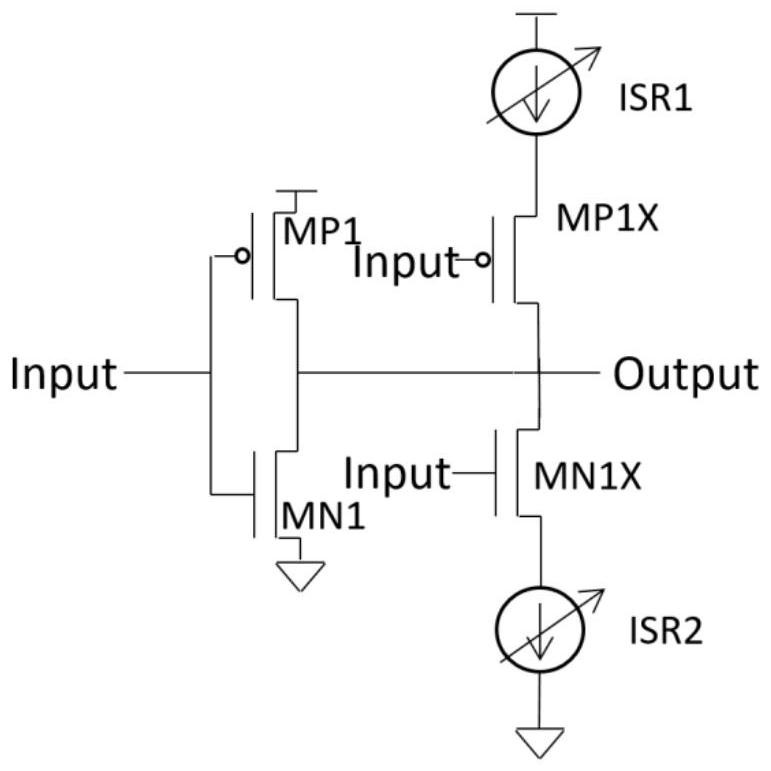
A technology of duty cycle correction and clocking, applied to electrical components, transforming continuous pulse chains into pulse chain devices with required modes, pulse processing, etc., can solve problems such as extra noise of current source ISR1/ISR2, and achieve saving The effects of area, low noise, and high calibration accuracy
- Summary
- Abstract
- Description
- Claims
- Application Information
AI Technical Summary
Problems solved by technology
Method used
Image

Examples
Embodiment Construction
[0016] The following will clearly and completely describe the technical solutions in the embodiments of the present invention with reference to the accompanying drawings in the embodiments of the present invention. Obviously, the described embodiments are only some, not all, embodiments of the present invention. Based on the embodiments of the present invention, all other embodiments obtained by persons of ordinary skill in the art without making creative efforts belong to the protection scope of the present invention.
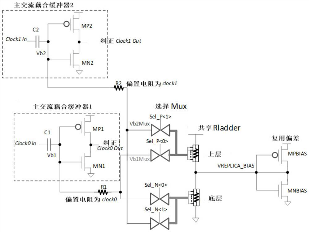
[0017] In the embodiment of the multi-channel shared clock duty ratio correction circuit of the present invention, the structural diagram of the multi-channel shared clock duty ratio correction circuit is as follows image 3 shown. image 3 Among them, the multi-channel shared clock duty cycle correction circuit includes multiple main AC-coupled buffers, a multiplexer Selection Mux, a shared resistor string Shared Rladder and a replica bias module Relica Bias,...
PUM
 Abstract
Description
Claims
Application Information
 - R&D
- Intellectual Property
- Life Sciences
- Materials
- Tech Scout
- Unparalleled Data Quality
- Higher Quality Content
- 60% Fewer Hallucinations
Browse by: Latest US Patents, China's latest patents, Technical Efficacy Thesaurus, Application Domain, Technology Topic, Popular Technical Reports.
© 2025 PatSnap. All rights reserved.Legal|Privacy policy|Modern Slavery Act Transparency Statement|Sitemap|About US| Contact US: help@patsnap.com