Switch with cable constraint protection for network technology

A network technology and switch technology, which is applied to the parts of the connecting device, the device of connecting/disconnecting the connecting parts, the electrical components, etc., can solve the problems such as the limitation of heat dissipation efficiency, and achieve the effect of enhancing stability and avoiding sliding

Active Publication Date: 2022-01-07
江苏品德网络科技有限公司
View PDF10 Cites 5 Cited by
  • Summary
  • Abstract
  • Description
  • Claims
  • Application Information

AI Technical Summary

Problems solved by technology

[0006] 3. The comparative document CN210670417U discloses a closed switch shell and switch, "including a front panel, a rear shell and a bottom plate, the front panel, the rear shell and the bottom plate are sealed and connected, and a partition is provided on the rear shell, and the partition divides the inside of the switch into two parts. The hardware room and the refrigeration room are sealed between the hardware room and the refrigeration room. The back shell and the bottom plate are provided with heat dissipation holes at the corresponding positions of the refrigeration room. The back shell is fixedly connected with a heat dissipation fan at the position of the heat dissipation holes. There is also a cooling component inside the switch. , the refrigeration component pumps the air in the hardware chamber into the refrigeration chamber to reduce the temperature and then sends it into the hardware chamber; the utility model isolates the inside of the switch from the outside through a sealed shell, thereby improving the waterproof and dustproof performance of the switch. The setting of the refrigeration component Improve the heat dissipation efficiency of the switch", the switch only uses the internal cooling components for cooling and cooling, and does not take into account that the switch needs to adjust the distance between the body to ensure the effective heat dissipation area in practical applications, so that the heat dissipation efficiency of the device is affected. limit;

Method used


Image

  • Switch with cable constraint protection for network technology
  • Switch with cable constraint protection for network technology
  • Switch with cable constraint protection for network technology

Examples


Embodiment 1

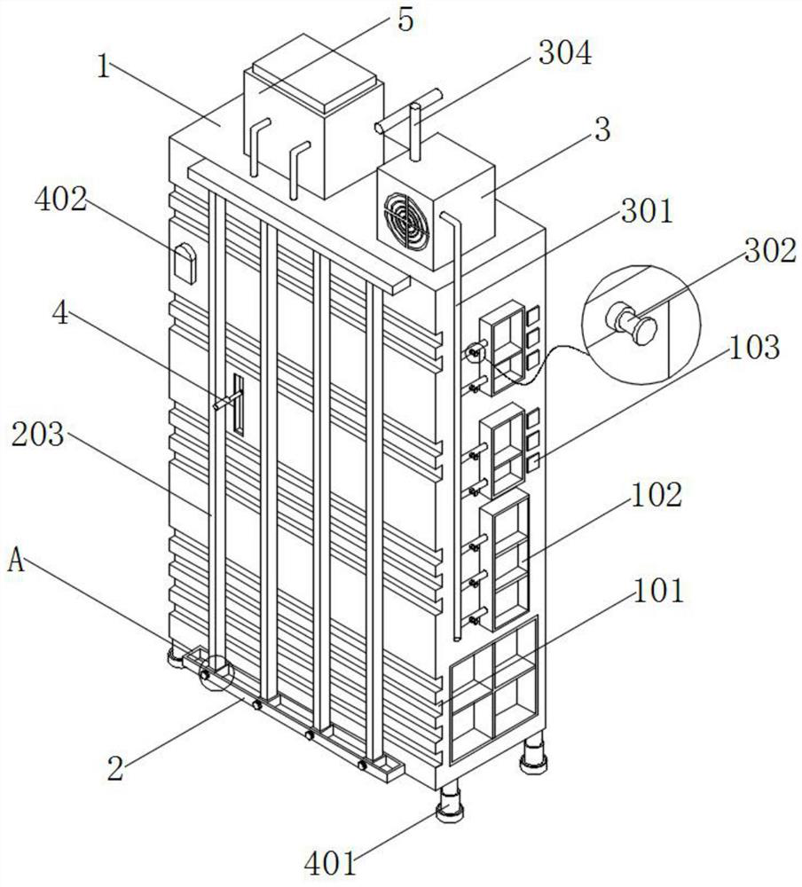
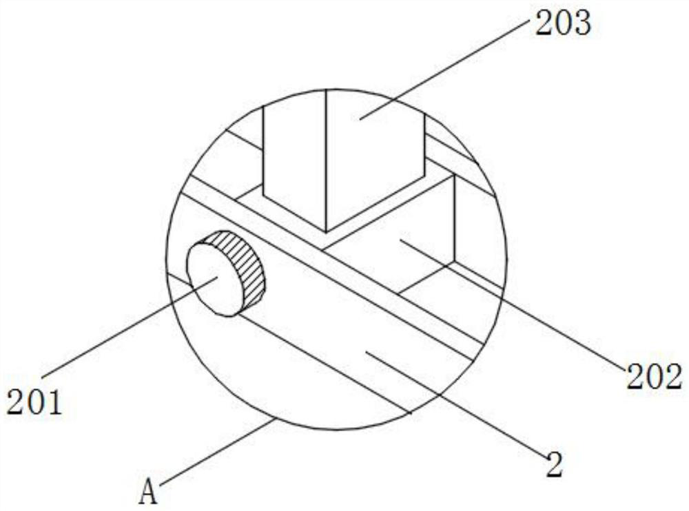
[0045] see Figure 1-Figure 2 , an embodiment provided by the present invention: a switch with cable restraint protection for network technology, including a switch case 1 and a harness control slot 2, the front of the switch case 1 is provided with a harness slot 101, the switch case The top and bottom of the front of the body 1 are equipped with iron wire harness control slots 2, and the inside of the wire harness control slot 2 is slidably installed with a moving magnetic block 202, and the surfaces of the moving magnetic blocks 202 are close to each other. The surface of 203 is attached to the surface of the wire harness groove 101, and the front side of the lower wire harness control groove 2 is connected with a magnet suction block 201, and the installation quantity of the magnet suction block 201 is consistent with the installation quantity of the interception rod 203;

[0046] One side surface of the switch housing 1 is equipped with a plug-in metal hole 102 and a stat...

Embodiment 2

[0051] see Figure 8 , an embodiment provided by the present invention: a switch with cable restraint protection for network technology, including an anti-fall electric push rod 7, and two groups of symmetrically arranged anti-fall electric push rods are installed on the bottom surface of the switch housing 1 Rod 7, an extension rod 701 is installed on the bottom of the anti-fall electric push rod 7, and an angle displacement sensor 702 is installed on the surface of the anti-fall electric push rod 7, and two groups of angle displacement sensors 702 are electrically connected to each other, and the angle displacement sensor 702 and the anti-fall electric push rod 702 are electrically connected to each other. The inverted electric push rod 7 is electrically connected, and a suction cup 703 is installed on the bottom of the extension rod 701 .

[0052] Specifically, when the shell of the switch shell 1 is tilted due to external force, one side of the bottom end of the switch she...

Embodiment 3

[0054] see figure 1 with Figure 4 , an embodiment provided by the present invention: a switch with cable restraint protection for network technology, including a misplaced heat dissipation structure 4, a misplaced heat dissipation structure 4 is installed on the front of the switch housing 1, and the misplaced heat dissipation structure 4 is located in the bundle In the middle of the trunking 101, the misplaced heat dissipation structure 4 includes an electric lifting column 401, an infrared range finder 402, a groove 403, a chute 404, an electronic telescopic rod 405 and an electromagnet 406. After the four corners of the bottom of the switch housing 1 are installed Electric lifting columns 401, and four sets of electric lifting columns 401 are located on the outside of two sets of anti-falling electric push rods 7, and the front of the switch housing 1 is equipped with an infrared rangefinder 402 and a groove 403, and the groove 403 is located on the outer side of the infra...


PUM


Abstract

The invention discloses a switch with cable constraint protection for the network technology, and the switch comprises a switch shell, wherein the top of the switch shell is provided with a dust removal and heat dissipation fan box and an immersion type cooling box, and the front surface of the switch shell is provided with a wire bunching groove. Iron wire harness control grooves are formed in the top and the bottom of the front face of the switch shell, intercepting rods are installed on the surfaces, close to each other, of movable magnetic attraction blocks, the surfaces of the intercepting rods are attached to the surfaces of wire harness grooves, and magnet attraction blocks are connected to the front face of the lower wire harness control groove in an attraction mode; the front surface of the switch housing is provided with a staggered heat dissipation structure, and the bottom surface of the switch housing is provided with two groups of symmetrically arranged anti-reverse electric push rods. By arranging the wire harness control groove and the dust removal and heat dissipation fan box, dust removal treatment can be carried out on the insertion position of the cable and the switch so as to enhance the connection effect of the cable joint and the switch, and the wire harness control groove and the dust removal and heat dissipation fan box are matched with each other to realize cable constraint.

Description

technical field [0001] The invention relates to the technical field of switches, in particular to a switch with cable restraint protection for network technology. Background technique [0002] The switch, as the main connection device of the LAN, differs from the router in that the switch is only used to distribute network data, the switch cannot handle the TCP / IP protocol, and the switch acts as an access point to expand the LAN rather than a router. , has gradually become the main network processing equipment in network data processing. [0003] The defect that existing switchboard exists is: [0004] 1. The comparative document CN211378172U discloses an embedded network switch including a network switch, "comprising a network switch, an organic casing is arranged on the network switch, and a through slot is correspondingly opened in the casing and at the position of the network switch, so Both sides of the top and bottom of the through groove and the center of the throu...

Claims


Application Information

Patent Timeline
Patent Type & Authority Applications(China)
IPC IPC(8): H04L49/10H04Q1/02H04Q1/04H01R13/502H01R13/62H01R13/629
CPCH04L49/10H04Q1/035H04Q1/04H01R13/629H01R13/502H01R13/6205
Inventor 胡玉华
Owner 江苏品德网络科技有限公司
Why Eureka
Try Eureka