Oral cavity CBCT equipment

A kind of equipment and oral technology, applied in the field of oral CBCT equipment, can solve problems such as growth, failure to meet different needs of different doctors, and equipment growth

Pending Publication Date: 2022-01-11
HEFEI MEIYA OPTOELECTRONICS TECH
View PDF0 Cites 1 Cited by
  • Summary
  • Abstract
  • Description
  • Claims
  • Application Information

AI Technical Summary

Problems solved by technology

Generally, the larger the area of ​​the detector, the larger the FOV, but the cost of the detector increases exponentially, and the cost of the equipment will also increase accordingly; the more the relative position (horizontal direction) of the detector and the X-ray source deviates , the larger D is, but this method cannot be adjusted steplessly and cannot meet the different needs of different doctors

Method used


Image

  • Oral cavity CBCT equipment
  • Oral cavity CBCT equipment
  • Oral cavity CBCT equipment

Examples


Embodiment approach

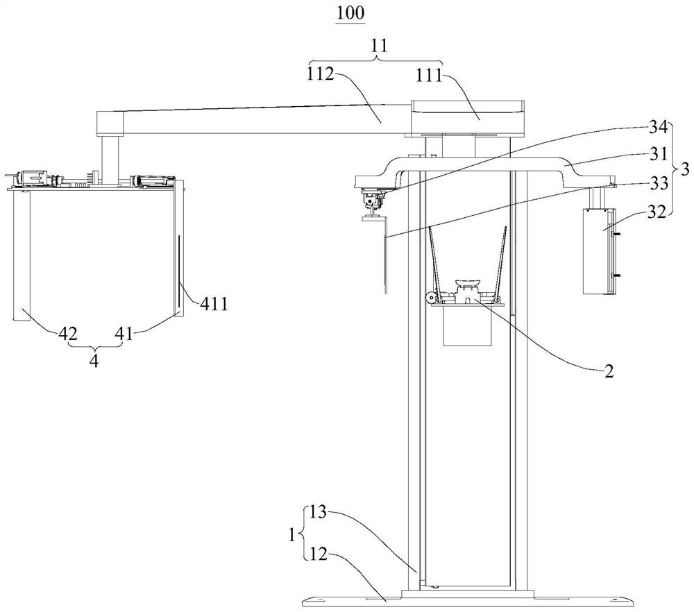
[0039] The FOV (imaging field of view) of the oral cavity CBCT device 100 , especially the size of the diameter D, can also be adjusted steplessly here. Its implementation is as follows:

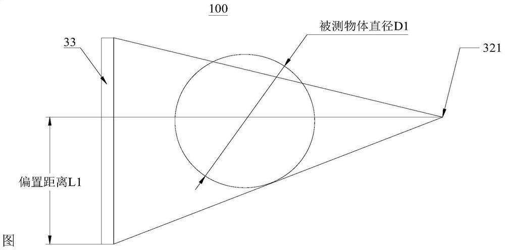
[0040] Such as image 3 As shown, the CT detection assembly moves to a certain position between the first position and the second position under the drive of the mobile drive assembly 34. At this time, the relative offset position between the X-ray source 321 and the lower edge of the CT detection assembly is L1, According to the imaging principle of oral cavity CBCT, the diameter of the measured object that it can contain is D1, that is, the diameter of the FOV is D1.

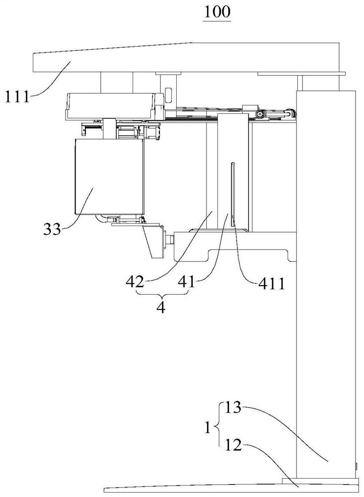
[0041] Such as Figure 4 As shown, the CT detection assembly is driven by the moving drive assembly 34 to move to another position between the first position and the second position. At this time, the relative offset position between the X-ray source 321 and the lower edge of the CT detection assembly is L2, The diameter ...


PUM


Abstract

The invention discloses an oral cavity CBCT equipment, a cantilever is arranged at the top of a supporting frame, and a supporting table is connected to the supporting frame and used for supporting the head of a patient. An X-ray assembly is arranged at one end of a C-shaped arm and the X-ray assembly is provided with an X-ray source. A CT detection assembly is arranged at the other end of the C-shaped arm, and the CT detection assembly and the X-ray assembly are located on the two opposite sides of the head of the patient. A movement driving assembly is used for driving the CT detection assembly to move between a first position and a second position. A head side position device comprises a secondary beam limiting device and a head side position detector, and the head side position detector is connected to the cantilever and used for receiving X-rays which come from the X-ray source and pass through the secondary beam limiting device. Wherein the CT detection assembly is used for receiving X-rays when being located at the first position, and the CT detection assembly is used for avoiding the X-rays from the X-ray source to the secondary beam limiting device when being located at the second position. According to the oral cavity CBCT equipment, the structure is simple, the production cost is low, the imaging view can be adjusted in a stepless mode, and the requirements of different doctors are met.

Description

technical field [0001] The invention belongs to the field of medical equipment, and in particular relates to oral cavity CBCT equipment. Background technique [0002] In related technologies, oral CBCT equipment (oral cone beam projection computerized tomography imaging equipment) often has the function of cephalometric imaging in order to meet the orthodontic needs of maxillofacial and whole head, and the principle of this function is a linear scan method. Due to the limitation of the overall layout of the equipment, it is necessary to keep the X-ray away from the CT detection component and its supporting parts when taking a cephalometric view. In order to solve this contradiction, the function is generally realized in the following ways. The first way is that the X-ray source rotates and the cephalometric detector moves; the second way is that the CT detection component is detachable and the head is shot Remove it when sideways. [0003] The disadvantage of the first met...

Claims


Application Information

Patent Timeline
IPC IPC(8): A61B6/14A61B6/03A61B6/00
CPCA61B6/4085A61B6/44A61B6/4429A61B6/4411A61B6/035A61B6/51
Inventor 张波徐明峰
Owner HEFEI MEIYA OPTOELECTRONICS TECH
Why Eureka
Try Eureka