
Garment processing excess material recovery device

A recovery device and residual material technology, applied in the direction of solid separation, filter screen, grid, etc., can solve the problems of crushing device damage, screen blockage, small stones, etc., and achieve the effect of high permeability

Inactive Publication Date: 2022-01-11
亳州新诚达时装有限公司
View PDF0 Cites 0 Cited by
  • Summary
  • Abstract
  • Description
  • Claims
  • Application Information

AI Technical Summary

Problems solved by technology

The rags are generally leftovers from clothing processing, or defective fabrics caused by cutting errors. After they are produced, people directly discard them on the ground. When work is over at night, they clean the ground uniformly and collect the rags. Then crush it through the crushing device, but this will cause small stones, dust and other impurities between the collected rags. The existence of gravel will cause damage to the crushing device, and too much dust and other impurities will make the inside of the equipment dirty. , and the cloth after crushing is not clean as a whole, and it needs to be cleaned again
[0004] When using a screen to filter dust, with the accumulation of dust and relatively large particles, it is easy to cause the screen to be blocked and affect the screening ability

Method used


Image

  • Garment processing excess material recovery device
  • Garment processing excess material recovery device
  • Garment processing excess material recovery device

Examples


Embodiment 1

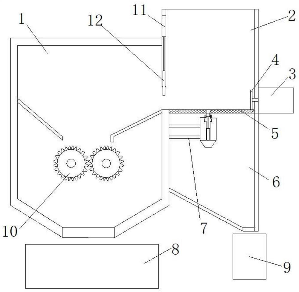
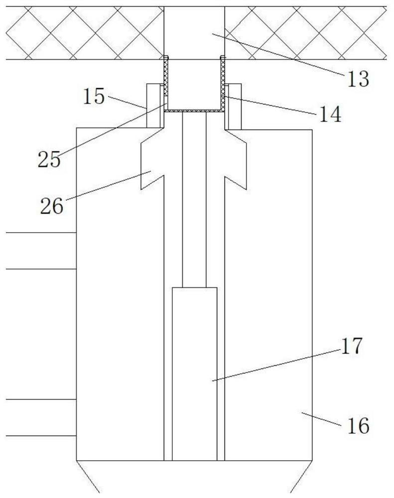
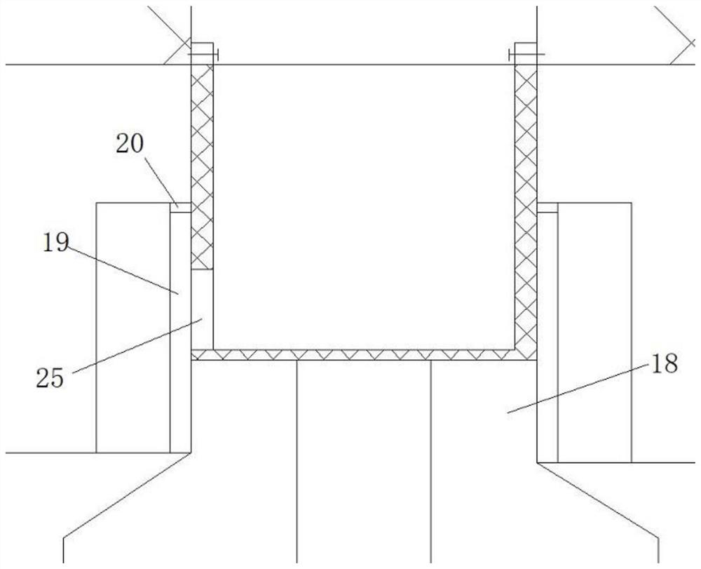
[0029] like Figure 1 to Figure 3 As shown, the screening mechanism includes a screening buffer box 2, a screen cloth 5 located at the bottom of the screening buffer case 2, and a particle separation mechanism located below the screen cloth 5. The feed port of 1 is connected, and the middle part of the screen 5 is provided with a through hole 13, and the particle separation mechanism drives the screen 5 to move downward to guide the collected impurity particles downward through the through hole 13. Among them, the aperture of the through hole is larger than the aperture of the screen. Since the screen has elastic deformation force, the particle separation mechanism drives the screen to move downward, and the relatively large particles will gather at the through hole in the middle of the screen, which is relatively convenient. Large particles of impurities are screened out through the through holes.

[0030] The particle separation mechanism comprises a separation box 16, a bu...

Embodiment 2

[0038] The difference between this embodiment and embodiment 1 is that, as Figure 4 and Figure 5 As shown, the lifting mechanism includes a drive motor 21, a rack 22 disposed in the cavity, and a gear 23 meshed with the rack 22. The gear 23 is installed in the cavity by rotating a shaft 24. The output of the drive motor 21 The end is connected with the rotating shaft 24, and the driving motor 21 rotates through the driving gear 23 so that the rack 22 drives the shielding plate 12 to move up and down. When setting, the gear is connected with the bearing on the inner wall of the cavity through one end of the rotating shaft, and the other end of the rotating shaft is connected with the output shaft of the driving motor through a coupling. When needing to open and close the feeding port of the pulverizing hopper, start the driving motor 21, the driving motor drives the gear to rotate, the gear drives the rack to move up and down in the cavity, and the rack drives the baffle pla...


PUM


Abstract

The invention provides a garment processing excess material recovery device. The device comprises a crushing material box, and a crushing assembly is arranged in the crushing material box. The recovery device further comprises a screening mechanism used for screening and removing impurity particles in the clothing excess materials, a guiding and conveying mechanism used for guiding the screened clothing excess materials to the crushing material box, a first storage structure used for storing the crushed materials guided out of the crushing material box and a second storage structure used for storing impurities screened out by the screening mechanism. According to the device, impurities can be well screened out before garment processing excess materials are crushed, large-particle impurities can be discharged downwards through through holes in the middle of a screen by continuously pulling the screen, the phenomenon that the large-particle impurities are gathered on the screen for a long time and block the screen is avoided, and the high permeability of the screen can be kept for a long time.

Description

technical field [0001] The invention relates to the technical field of clothing waste recovery, in particular to a garment processing waste recovery device. Background technique [0002] Due to the continuous improvement of human living standards, the demand for clothes continues to increase, and there will be a lot of surplus materials of different sizes in the process of clothing processing and production, such as scraps of cloth. A lot of pollution. [0003] In order to recycle waste resources, the current common practice is to uniformly pack discarded clothing fabrics for crushing, and the crushed fabrics are used as fillers for some clothing or other items. The rags are generally leftovers from clothing processing, or defective fabrics caused by cutting errors. After they are produced, people directly discard them on the ground. When work is over at night, they clean the ground uniformly and collect the rags. Then crush it through the crushing device, but this will ca...

Claims


Application Information

Patent Timeline
Patent Type & Authority Applications(China)
IPC IPC(8): B02C4/08B02C4/30B02C4/42B02C23/02B02C23/08B07B1/34B07B1/42B07B1/46
CPCB02C4/08B02C4/30B02C4/42B02C23/02B02C23/08B07B1/343B07B1/42B07B1/46B02C2201/06
Inventor 盛爱良陶雪华
Owner 亳州新诚达时装有限公司
Learn More