Ultrahigh-speed movable column type gantry machining center

A processing center, ultra-high-speed technology, applied in the direction of metal processing equipment, metal processing machinery parts, manufacturing tools, etc., can solve the problems of the movement accuracy of the column to be improved, so as to improve the service life, improve the stability and reduce the thermal wear Effect

Pending Publication Date: 2022-01-11
CHANGZHOU TRANSCEND CNC MACHINE TOOL
View PDF0 Cites 0 Cited by
  • Summary
  • Abstract
  • Description
  • Claims
  • Application Information

AI Technical Summary

Problems solved by technology

[0005] The purpose of the present invention is to provide an ultra-high-speed moving column type gantry machining center, which solves the problem that the accuracy of the column movement of the ultra-high-speed gantry machining center needs to be improved in the prior art

Method used


Image

  • Ultrahigh-speed movable column type gantry machining center
  • Ultrahigh-speed movable column type gantry machining center
  • Ultrahigh-speed movable column type gantry machining center

Examples


Embodiment 1

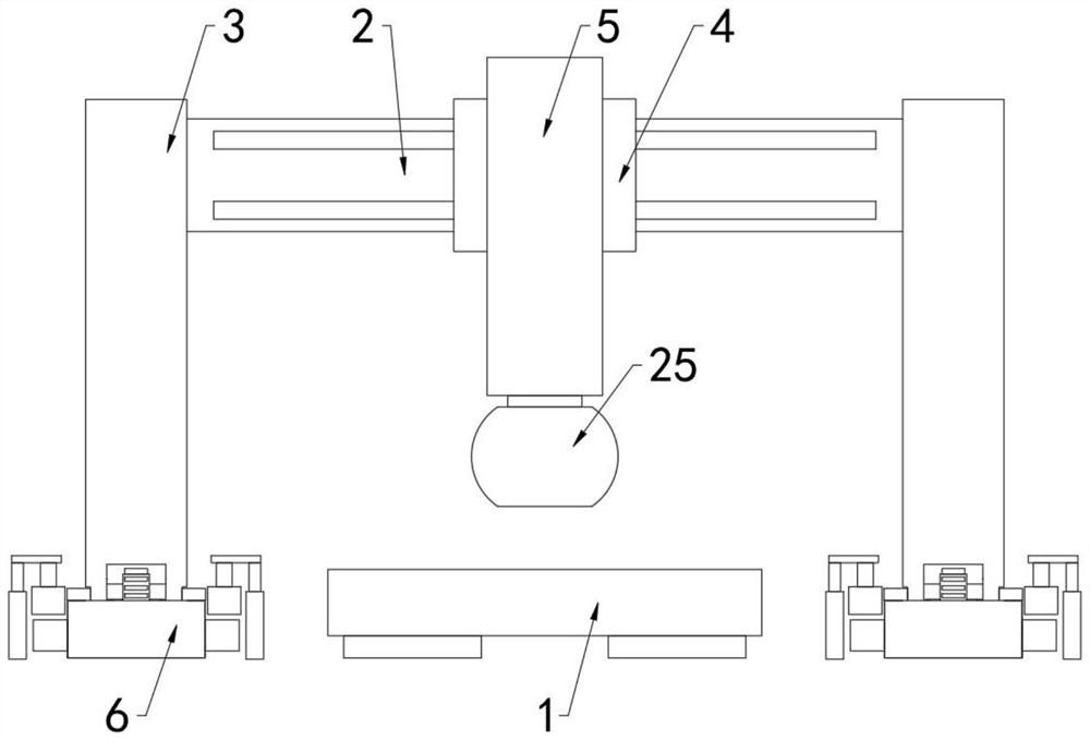
[0030] refer to Figure 1-4 , an ultra-high-speed moving column type gantry machining center, including a workbench 1, a beam 2 arranged above the workbench 1, a ram 4 arranged on the beam 2, a ram 5 installed on the ram 4 and a The processing cutter die 25 at the bottom of the spool 5 also includes:

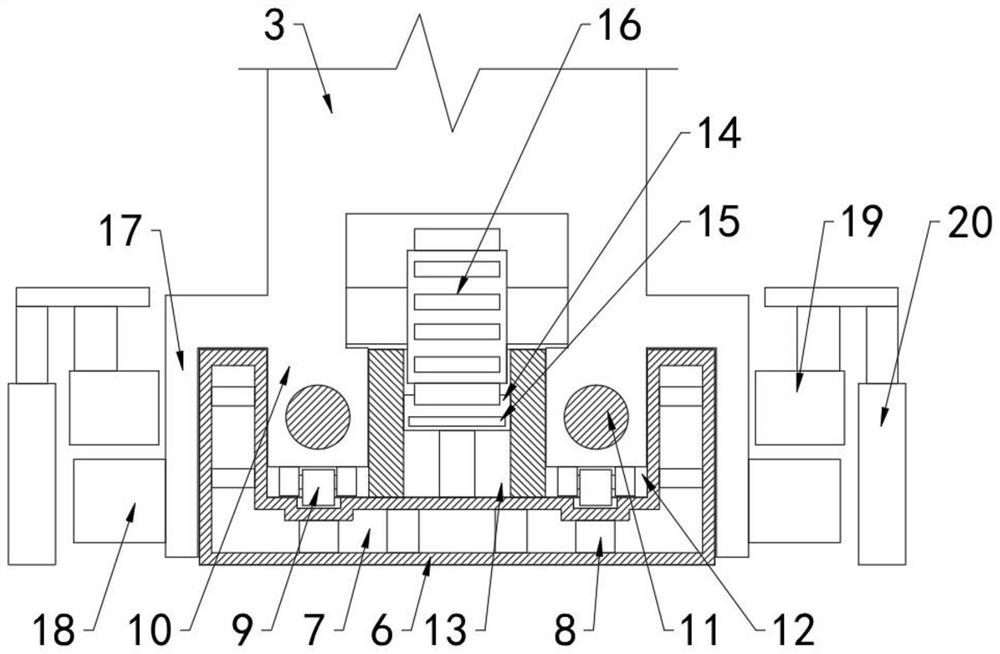
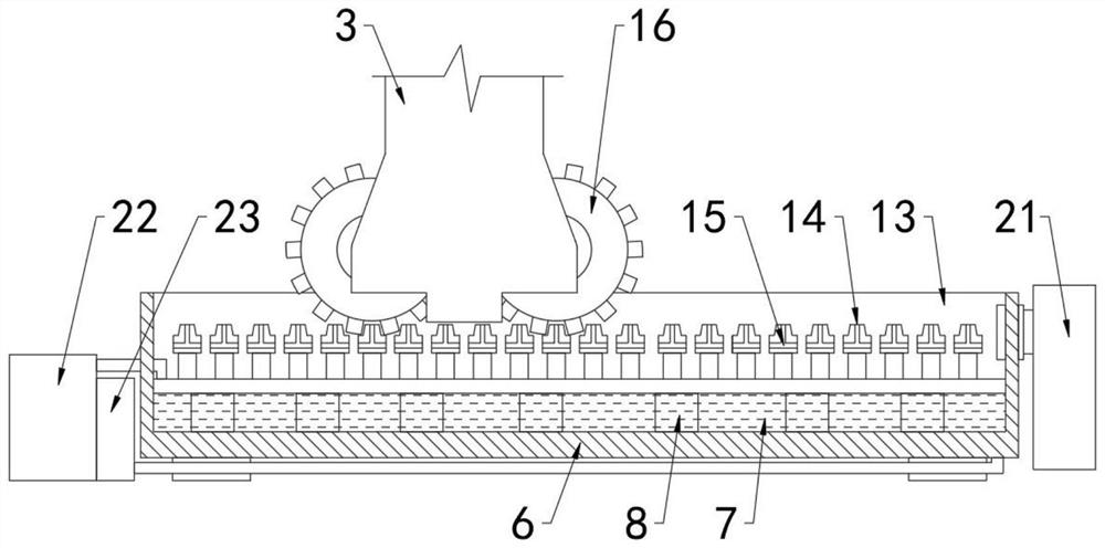
[0031] Fixed seat 6, fixed seat 6 is symmetrically provided with two groups, and fixed seat 6 top is symmetrically provided with two moving grooves 12, and between two moving grooves 12 is supporting groove 13, is linear equidistant in supporting groove 13 and is provided with multiple a positioning tooth 14, the inside of the fixed seat 6 is provided with a water-cooling cavity 7, and circulating water is provided in the water-cooling cavity 7;

[0032] Column 3, two groups of columns 3 are symmetrically arranged, and the tops of the two groups of columns 3 are installed with the two ends of the beam 2, the bottom ends of the two groups of columns 3 are respectively limited in...

Embodiment 2

[0036] refer to Figure 1-4 , an ultra-high-speed moving column type gantry machining center, including a workbench 1, a beam 2 arranged above the workbench 1, a ram 4 arranged on the beam 2, a ram 5 installed on the ram 4 and a The processing die 25 at the bottom of the sliding column 5 also includes: a fixed seat 6, which is symmetrically provided with two groups, and the top of the fixed seat 6 is symmetrically provided with two moving grooves 12, and between the two moving grooves 12 is a supporting groove 13. A plurality of positioning teeth 14 are provided in a linear equidistant manner in the support groove 13, and a water cooling chamber 7 is provided inside the fixed seat 6, and circulating water is provided in the water cooling chamber 7; the columns 3 and 3 are symmetrically arranged in two groups, and The tops of the two sets of columns 3 are installed on both ends of the crossbeam 2, the bottom ends of the two sets of columns 3 are respectively limited in the two ...

Embodiment 3

[0041] refer to Figure 1-4 , an ultra-high-speed moving column type gantry machining center, including a workbench 1, a beam 2 arranged above the workbench 1, a ram 4 arranged on the beam 2, a ram 5 installed on the ram 4 and a The processing die 25 at the bottom of the sliding column 5 also includes: a fixed seat 6, which is symmetrically provided with two groups, and the top of the fixed seat 6 is symmetrically provided with two moving grooves 12, and between the two moving grooves 12 is a supporting groove 13. A plurality of positioning teeth 14 are provided in a linear equidistant manner in the support groove 13, and a water cooling chamber 7 is provided inside the fixed seat 6, and circulating water is provided in the water cooling chamber 7; the column 3 and the column 3 are symmetrically arranged in two groups, and The tops of the two sets of columns 3 are installed on the two ends of the crossbeam 2, the bottom ends of the two sets of columns 3 are respectively limite...


PUM


Abstract

The invention relates to the technical field of gantry machining centers, in particular to an ultrahigh-speed movable column type gantry machining center, and solves the problem that the moving accuracy of a stand column of an ultrahigh-speed gantry machining center needs to be improved in the prior art. The ultrahigh-speed movable column type gantry machining center comprises a workbench, a cross beam arranged above the workbench, a ram arranged on the cross beam, a sliding column installed on the ram and a machining cutting die installed at the bottom end of the sliding column, and further comprises two sets of fixing bases symmetrically arranged, and two moving grooves are symmetrically formed in the tops of the fixing bases. According to the ultrahigh-speed movable column type gantry machining center, when a stand column stopping command is started, speed stopping plates rapidly move downwards till positioning toothed plates connected with outer side plates are vertically connected in an inserted mode so as to limit inertial motion of stand columns, braking of inertial motion of the ultrahigh-speed movable column type gantry machining center is achieved through the up-and-down insertion meshing mode of teeth, and therefore the stability and the accuracy of high-speed movement of the loaded stand columns are realized.

Description

technical field [0001] The invention relates to the technical field of gantry machining centers, in particular to an ultra-high-speed movable column gantry machining center. Background technique [0002] The gantry machining center refers to the machining center where the axis of the Z axis of the main shaft is perpendicular to the workbench. The overall structure is a large machining center with a portal structure frame composed of double columns and top beams. There is a beam in the middle of the double columns. There are many types of gantry machining centers, including fixed beam type (fixed beam, moving / rotating workbench), moving beam type (beam moves up and down, workbench moves back and forth), moving column type (fixed workbench, gantry moves), crane type (The table is fixed and the beam moves) There are also many types of gantry machining centers with the above composite forms. The processing characteristics, capabilities, and targeted product processing uses are ...

Claims


Application Information

Patent Timeline
Patent Type & Authority Applications(China)
IPC IPC(8): B23Q1/25B23Q11/12
CPCB23Q1/25B23Q11/12
Inventor 曹浩郑伶俐赖立迅徐伟尤伟曹强
Owner CHANGZHOU TRANSCEND CNC MACHINE TOOL
Why Eureka
Try Eureka