Stacking machine

A stacker and detection mechanism technology, applied in the direction of hoisting devices, lifting equipment safety devices, etc., can solve the problems of complex overall structure, high cost, and inconvenient maintenance and maintenance, and achieve high safety, rapid response, and simple structure Effect

Active Publication Date: 2022-01-11
SAFE RUN & HISCENT MACHINERY SUZHOU
View PDF5 Cites 1 Cited by
  • Summary
  • Abstract
  • Description
  • Claims
  • Application Information

AI Technical Summary

Problems solved by technology

[0003] 1. The traditional fall prevention mechanism adopts the principle of sliding cooperation between the movable wedge and the inclined surface of the fixed wedge for self-locking to prevent falling. Since the cargo platform falls rapidly when the rope is broken, in order to ensure good self-locking performance, the movable wedge It needs to move upward relative to the fixed wedge, that is, to move in the opposite direction to the movement of the stage; in order to achieve this function, the traditional fall prevention mechanism needs to be equipped with an additional speed limiting mechanism to pull the movable wedge upward when the rope is broken , or through a reversing mechanism (such as a pulley block mechanism) connected to the wire rope to convert the upward pulling force of the wire rope into a downward force on the movable wedge in the normal state. The overall structure of the above two methods is relatively complicated. higher cost
[0004] 2. In order to achieve better safety, the traditional anti-fall mechanism is set between the loading platform and the stacker column. When the anti-fall mechanism and the broken rope detection mechanism need maintenance or replacement, the loading platform needs to be removed from the The corresponding operation can only be carried out by removing the column, so it has the problem of inconvenient maintenance

Method used


Image

  • Stacking machine
  • Stacking machine
  • Stacking machine

Examples


Embodiment Construction

[0058] The above solution will be further described below in conjunction with specific embodiments. It should be understood that these examples are used to illustrate the present invention and not to limit the scope of the present invention. The implementation conditions used in the examples can be further adjusted according to the conditions of specific manufacturers, and the implementation conditions not indicated are usually the conditions in routine experiments.

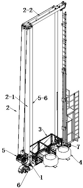
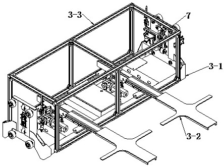
[0059] see figure 1 , which is a structural schematic diagram of an embodiment of the present invention, provides a stacker, including a base 1, a door frame mechanism 2 installed on the base 1, and a loader installed inside the door frame mechanism 2 and can be raised and lowered relative to the door frame mechanism 2. The object stage mechanism 3 and the lifting drive mechanism 5 which is transmission-connected with the object stage mechanism 3 to drive the object stage mechanism 3 to move up and down.

[006...


PUM


Abstract

The invention discloses a stacking machine. The stacking machine comprises a base, a portal frame mechanism, an object carrying table mechanism and a lifting driving mechanism, and the base is provided with a walking mechanism; the portal frame mechanism is mounted on the base; the object carrying table mechanism is mounted on the inner side of the portal frame mechanism and can ascend and descend relative to the portal frame mechanism; the lifting driving mechanism is in transmission connection with the object carrying table mechanism to drive the object carrying table mechanism to move up and down, and comprises a driving assembly and a transmission part connected with the driving assembly and the object carrying table mechanism; a broken rope detection mechanism and an anti-falling mechanism are arranged on one side, away from the portal frame mechanism, of the object carrying table mechanism; the broken rope detection mechanism is fixedly connected with the transmission part; and the anti-falling mechanism comprises a triggering assembly and a locking assembly, the triggering assembly comprises a lever mounted on the locking assembly, an elastic assembly connecting the first end of the lever and the locking assembly, and a connecting rod assembly connecting the first end of the lever and the broken rope detection mechanism. The stacking machine is good in safety.

Description

technical field [0001] The invention relates to the technical field of intelligent storage equipment, in particular to a high-speed stacker for semi-steel blank storage. Background technique [0002] The automated three-dimensional warehouse plays an important role in material storage. It is usually set up with several floors, dozens of floors, or even dozens of floors. The stacker is an important equipment for the automated three-dimensional warehouse, which is responsible for delivering the goods to the designated location. With the rapid development of the logistics system, the stacker is required to have a higher operating speed and reliable safety performance, and the anti-fall performance of the stacker is particularly important, so the stacker needs to be equipped with an anti-fall mechanism, but the traditional stacker The anti-fall mechanism of the stacker needs to be used in conjunction with the speed limiting mechanism, so there are the following deficiencies: ...

Claims


Application Information

Patent Timeline
Patent Type & Authority Applications(China)
IPC IPC(8): B66F17/00B66F9/07
CPCB66F17/003B66F9/07
Inventor 蒋晶李彦海祝洪文
Owner SAFE RUN & HISCENT MACHINERY SUZHOU
Why Eureka
Try Eureka