Automatic screwing-on and screwing-off device of sucker rod for oil field

A sucker rod, automatic technology, applied in drill pipes, drilling equipment, earthwork drilling, etc., can solve the problems of deflection of sucker rod shackle, many tools for making and breaking, and low efficiency, so as to avoid loosening and strengthen Assembly effect, the effect of improving work efficiency

Active Publication Date: 2022-01-11
智慧猫东营智能科技有限公司
View PDF20 Cites 4 Cited by
  • Summary
  • Abstract
  • Description
  • Claims
  • Application Information

AI Technical Summary

Problems solved by technology

[0004] In order to overcome the problem that the existing make-up and breakout tools are many and discrete, manual hand-held tools are required for auxiliary disassembly, the efficiency is extremely low, and it is difficult to solve the shortcomings of micro-deflection when the sucker rod is breakout, the invention provides an automatic sucker rod for oil field. Shackle

Method used


Image

  • Automatic screwing-on and screwing-off device of sucker rod for oil field
  • Automatic screwing-on and screwing-off device of sucker rod for oil field
  • Automatic screwing-on and screwing-off device of sucker rod for oil field

Examples


Embodiment 1

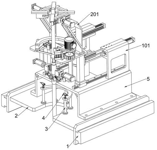
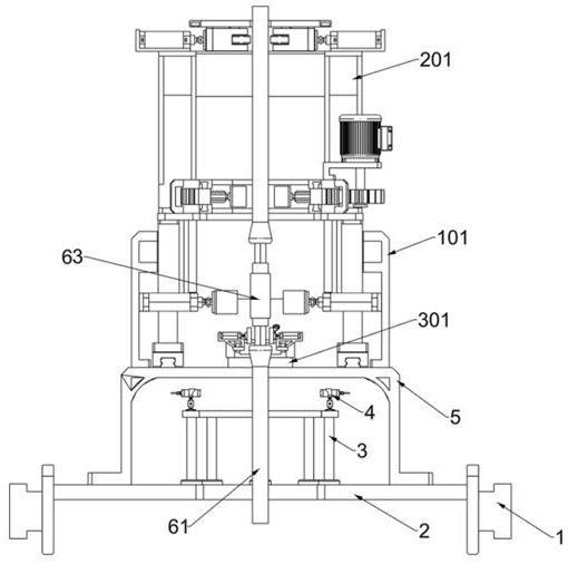
[0030] An automatic screw-on and break-out device for a sucker rod used in an oil field, such as Figure 1-3 As shown, it includes a guide mounting plate 1, a working base plate 2, a second support frame 5, a clamping and twisting system, a positive position system and an adaptive clamping system; the opposite sides of the two guide mounting plates 1 are connected with a working base plate 2; The upper surface of the working base plate 2 is connected with the second support frame 5; the upper surface of the second support frame 5 is connected with the clamping knob system; the upper part of the clamping knob system is connected with the positive positioning system; There is an adaptive snap-in system.

[0031] The left part of the working base plate 2 has a U-shaped groove.

[0032] It also includes a first support frame 3 and a monitoring positioning member 4; the upper surface of the working base 2 is fixed with the first support frame 3; the upper surface of the first supp...

Embodiment 2

[0035] On the basis of Example 1, such as figure 1 and Figure 4-6 As shown, the clamping knob system includes a first support plate 101, a first electric telescopic member 102, a third support frame 103, a support slider 104, a first straight slide rail 105, a second support plate 106, a second electric Telescopic piece 107, first arc-shaped clamp 108, arc-shaped slide rail 109, gear ring 1010, first fixed plate 1011, third electric telescopic piece 1012, second arc-shaped clamp 1013, third support plate 1014, motor 1015 and flat Gear 1016; the upper surface of the second support frame 5 is fixed with two symmetrical and parallel first support plates 101; each of the two first support plates 101 is connected with a first electric telescopic member 102 by bolts; two first electric telescopic members 102, the telescopic part is fixedly connected with a third support frame 103; the bottom of the third support frame 103 is welded with two symmetrical support sliders 104; the upp...

Embodiment 3

[0042] On the basis of Example 2, such as Figure 10 As shown, the adaptive clamping system includes a sixth support frame 301, an electric slide rail 302, an electric slider 303, a third fixed plate 304, a seventh support frame 305, a fifth electric telescopic member 306, straight-nose pliers 307, Fixed frame 308 and distance measurer 309; The left part of the upper surface of the second support frame 5 is fixedly connected with the sixth support frame 301; The left part of the sixth support frame 301 is fixedly connected with the electric slide rail 302; Electric slider 303; a third fixed plate 304 is fixedly connected to the electric slider 303; two symmetrical seventh support frames 305 are welded on the third fixed plate 304; each of the two seventh support frames 305 is fixed with a The fifth electric telescopic part 306; each of the telescopic parts of the two fifth electric telescopic parts 306 is fixedly connected with a straight-nose pliers 307; Each is fixedly conn...


PUM


Abstract

The invention relates to the field of oil field workover treatment equipment, in particular to an automatic screwing-on and screwing-off device of a sucker rod for an oil field. The technical problems to be solved are that the existing screwing-on and screwing-off tools are many and discrete, the tools need to be manually held to assist in disassembling, the efficiency is extremely low, and the problem of micro deflection during screwing-off of a sucker rod is difficult to solve. According to the technical scheme, the automatic screwing-on and screwing-off device of the sucker rod for the oil field comprises guide installing plates and a working bottom plate, wherein opposite sides of the two guide installing plates are connected with the working bottom plate. According to the automatic screwing-on and screwing-off device, an operation mode of mutual cooperation of manual work is abandoned; a screwing-off tool is integrated; screwing-on and screwing-off between the sucker rods are automatically completed in the whole process; the sucker rod above a coupling is disassembled in the screwing-off process; connection between the coupling and the sucker rod at the lower part is not influenced; loosening is avoided; meanwhile, the screwing-on and screwing-off sucker rod is corrected; the assembly effect between the sucker rod and the coupling is enhanced; the use safety of the sucker rod is improved; and the working efficiency during oil well maintenance is greatly improved.

Description

technical field [0001] The invention relates to the field of oil field workover equipment, in particular to an automatic make-up and break-out device for sucker rods used in oil fields. Background technique [0002] Oilfield workover operations need to pull out and lower the sucker rod in the well, but the sucker pipes are connected by couplings, and the make-up and break-out of the sucker rods requires the cooperation of two operators. The existing auxiliary make-up and break-out tools are relatively discrete , it is impossible to construct a set of breakout tools and locate them on the workover platform. The operator needs to change the tool continuously to complete the breakout and breakout, and it is difficult to remove the sucker rod easily when the sucker rod is slightly deflected. At the same time, the existing equipment does not pay attention to the problem of sucker rod deflection, which brings great troubles to the operator for disassembly and installation, and req...

Claims


Application Information

Patent Timeline
Patent Type & Authority Applications(China)
IPC IPC(8): E21B19/16
CPCE21B19/164E21B19/165
Inventor 塔拉
Owner 智慧猫东营智能科技有限公司
Why Eureka
Try Eureka