Supercharge Your Innovation With Domain-Expert AI Agents!

Assembly mechanism for increasing torque of hydraulic retarder

A hydraulic retarder and retarder technology, applied in the direction of liquid resistance brakes, mechanical equipment, brake types, etc., can solve unfavorable mass production and assembly, inability to install directly, reduction of effective diameter of retarder output shaft, etc. problems, to achieve the effect of protecting life and property safety, improving assembly efficiency, and ensuring mechanical properties

Pending Publication Date: 2022-01-11
吉林省中誉信德科技有限公司
View PDF0 Cites 0 Cited by
  • Summary
  • Abstract
  • Description
  • Claims
  • Application Information

AI Technical Summary

Problems solved by technology

[0003] At present, the best place to install the hydraulic retarder on the market is in the right area of ​​the auxiliary case of the automobile transmission. This area is limited by the structure of the auxiliary case of the transmission and the frame of the vehicle, and it is impossible to increase the driving wheel, a key part of the retarder to generate braking torque. and fixed wheel outer circle diameter D, so that the braking torque effect cannot be improved, and the braking requirements of existing large-tonnage vehicles and large-slope road sections cannot be met.
[0004] In order to improve the greater deceleration effect and braking torque, it is the best and effective method to increase the blade length L value on the moving wheel and the fixed wheel. However, increasing the L value reduces the direct B area of ​​the moving wheel and the fixed wheel, resulting in The effective diameter of the output shaft of the retarder is reduced, resulting in insufficient performance of the output shaft. At the same time, the tapered roller bearing cannot be directly installed on the output shaft. If a small tapered roller bearing is selected, it cannot meet the requirements of high load and large braking torque. At the same time, it is not conducive to the adjustment of bearing free clearance, and it is not conducive to mass production and assembly. Therefore, in order to solve such problems, we propose a component mechanism for hydraulic retarder torque increase

Method used


Image

  • Assembly mechanism for increasing torque of hydraulic retarder
  • Assembly mechanism for increasing torque of hydraulic retarder

Examples


Embodiment

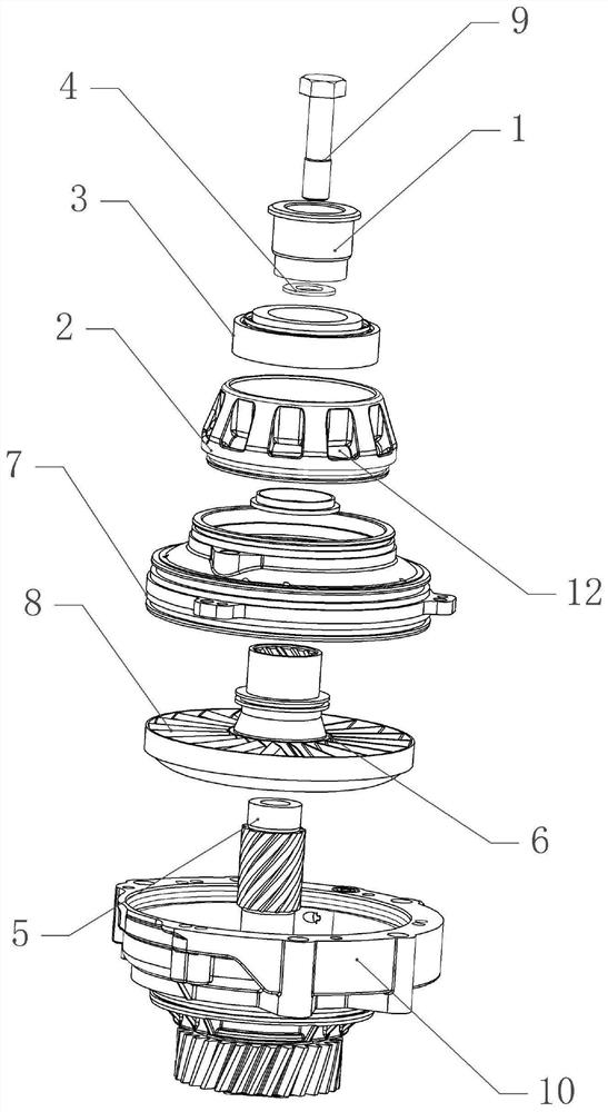
[0028] Basic as attached figure 1 And attached figure 2 As shown, a component mechanism for increasing the torque of a hydraulic retarder includes a retarder housing 10, the upper bolt of the retarder housing 10 is fixed with a bearing race 2, and the circumference of the bearing race 2 is provided with several The oil inlet hole 12 and the bearing race 2 are coaxially fixed with a bearing 3, and the bearing 3 in this embodiment is a tapered roller bearing.

[0029] A shaft diameter ring 1 is coaxially fixed inside the bearing 3, and the shaft diameter ring 1 is coaxially fixed with a retarder output shaft 5, and the end of the retarder output shaft 5 is threaded to a limit piece, and the limit piece is a limit bolt 9 , the limit bolt 9 rotates with the retarder housing 10, that is, the limit bolt 9 limits the retarder output shaft 5. A free gap adjustment block 4 is arranged between the shaft diameter ring 1 and the output shaft 5 of the retarder, and the free gap adjustme...


PUM


Abstract

The invention belongs to the technical field of hydraulic retarder auxiliary assemblies and provides an assembly mechanism for increasing torque of a hydraulic retarder. The assembly mechanism comprises a retarder shell, a bearing race fixed on the retarder shell and a bearing coaxially mounted on the bearing race, wherein a shaft diameter ring is coaxially arranged in the bearing; a retarder output shaft is coaxially fixed on the shaft diameter ring; the retarder output shaft is connected with a limiting part matched with the retarder shell in a rotating mode; a free gap adjusting block sleeved on the limiting part is arranged between the shaft diameter ring and the retarder output shaft; the retarder output shaft is coaxially connected with a movable wheel through a connecting part; and a fixed wheel fixed on retarder shell is arranged on the outer side of the movable wheel. According to the assembly mechanism for increasing the torque of the hydraulic retarder, L values of fixed wheel blades are increased; the brake torque of the retarder is improved; the mechanical property of the output shaft is ensured; a rolling bearing structure with high load and high rotating speed is met; the brake effects of high-speed running and long steep slopes of existing large-tonnage vehicles are met; and the safety of life and property of people is protected.

Description

technical field [0001] The invention belongs to the technical field of auxiliary components of a hydraulic retarder, and in particular relates to a component mechanism for increasing the torque of a hydraulic retarder. Background technique [0002] The stator of the hydraulic retarder is also the retarder housing, which is connected to the rear end of the transmission or the frame. The rotor is connected to the transmission shaft through a hollow shaft. Both the rotor and the stator are cast with blades. When working, with the help of the control valve Manipulate to apply pressure to the oil pool, so that the working fluid is filled into the working chamber between the rotor and the stator. When the rotor rotates, a torque is applied to the stator through the working fluid, and the reverse torque of the stator becomes the braking torque of the rotor. Its value depends on the liquid volume and pressure in the working chamber (depending on the brake strength gear set by the co...

Claims


Application Information

Patent Timeline
Patent Type & Authority Applications(China)
IPC IPC(8): F16D57/02
CPCF16D57/02
Inventor 李超伦王键张士城
Owner 吉林省中誉信德科技有限公司
Features
  • R&D
  • Intellectual Property
  • Life Sciences
  • Materials
  • Tech Scout
  • Unparalleled Data Quality
  • Higher Quality Content
  • 60% Fewer Hallucinations
Learn More