Hydraulic suspension decoupling vibration isolation device

A hydraulic suspension and decoupling technology, applied in the direction of shock absorber, shock absorber-spring combination, spring/shock absorber, etc., can solve problems such as affecting the backflow of damping fluid, affecting the car experience, and abnormal sound of cavitation , to achieve a stable shock absorption effect and improve the riding experience

Pending Publication Date: 2022-01-11
建新赵氏科技股份有限公司
View PDF12 Cites 0 Cited by
  • Summary
  • Abstract
  • Description
  • Claims
  • Application Information

AI Technical Summary

Problems solved by technology

[0003] In the traditional hydraulic mount decoupling vibration isolation mechanism, when the damping fluid moves upward, the liquid cannot open the decoupling plate, and the lower liquid chamber will generate negative pressure, resulting in cavitation noise; the failure of the decoupling plate to open will affect the damping fluid. Backflow, resulting in poor shock absorption effect of the decoupling vibration isolation mechanism of the hydraulic mount, and the abnormal noise generated by the negative pressure of the lower liquid chamber will also affect the car experience

Method used


Image

  • Hydraulic suspension decoupling vibration isolation device
  • Hydraulic suspension decoupling vibration isolation device
  • Hydraulic suspension decoupling vibration isolation device

Examples


Embodiment 1

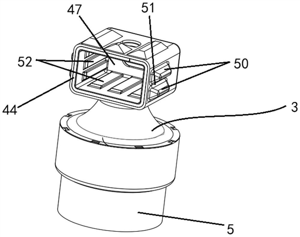
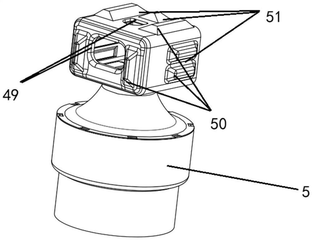
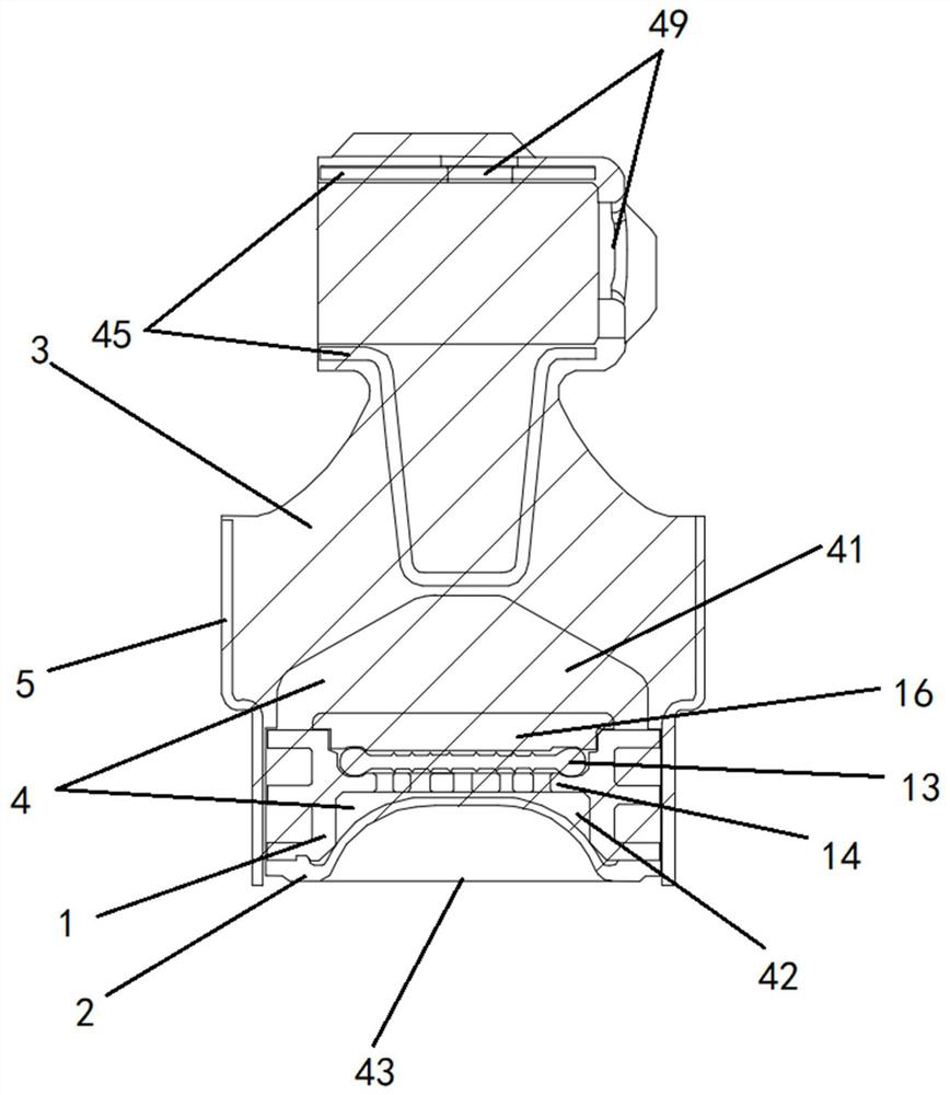
[0044] Such as Figure 1-10As shown, a hydraulic suspension decoupling vibration isolation device includes a valve body 1, and the valve body 1 includes a through hole 11 and a flow channel 12; the through hole 11 is set in the valve body 1, and the flow channel 12 is set in the valve body 1; a flow channel opening 121 is provided in the flow channel 12, and the through hole 11 and the flow channel 12 communicate through the flow channel opening 121; a decoupling plate 13 and a flow limiting plate 14 are provided in the through hole 11, and the Passing holes 15 are distributed on the restrictor plate 14, and the level of the restrictor plate 14 is higher than the level of the flow channel opening 121, and the decoupling plate 13 covers the upper surface of the restrictor plate 14; The plate 14 defines the position of the decoupling disk 13, so that the decoupling disk 13 is in a position that is convenient to open, and then the decoupling disk 13 can be opened when the damping...

Embodiment 2

[0064] Such as Figure 11-12 As shown, in this embodiment, the flow channel includes a flow channel inlet 122 and two flow channel openings 121; the flow channel opening 121 includes a first flow channel outlet 61 and a second flow channel outlet 62, and the flow channel inlet 122 and the second flow channel outlet 62 are arranged at both ends of the flow channel, and the first flow channel outlet 61 is arranged between the flow channel inlet 122 and the second flow channel outlet 62, and the height of the first flow channel outlet 61 is lower than the flow limit The horizontal height of the plate; between the channel inlet 122 and the first channel outlet 61 is the first channel 64, between the first channel outlet 61 and the second channel outlet 62 is the second channel 65, and the first channel outlet 61 Make the through hole communicate with the first flow channel 64 and the second flow channel 65; the flow channel communicates with the upper liquid chamber 41 through the...


PUM


Abstract

The invention discloses a hydraulic suspension decoupling vibration isolation device which comprises a valve body. The valve body comprises a through hole and a flow channel, the through hole is formed in the valve body, and the flow channel is formed in the outer surface of the valve body. A flow channel opening is formed in the flow channel, and the through hole communicates with the flow channel through the flow channel opening. A decoupling disc and a flow limiting plate are arranged in the through hole, clearing holes are distributed in the flow limiting plate, the horizontal height of the flow limiting plate is higher than that of the flow channel opening, and the upper surface of the flow limiting plate is covered with the decoupling disc; the position of the decoupling disc is limited through the flow limiting plate, so that the decoupling disc is located at the position convenient to open, then the damping liquid can open the decoupling disc when moving upwards, the damping effect is guaranteed, the situation that the decoupling disc blocks the through hole, negative pressure is generated in a liquid chamber, and accordingly abnormal sound of a cavity is caused is avoided, and the riding experience of a vehicle is further improved; and through the distributed clearing holes, the damping liquid is more stable when passing through the flow limiting plate, and then the damping effect of the device is more stable.

Description

technical field [0001] The invention relates to the field of design and manufacture of shock absorbing devices, more specifically, to a hydraulic mount decoupling vibration isolation device. Background technique [0002] The hydraulic vibration isolation device is a commonly used vibration isolation device in existing equipment. Compared with other types of vibration isolation devices, the vibration isolation effect of the hydraulic vibration isolation device is more gentle and stable; therefore, it is often used in automobiles. To bring passengers a good and comfortable ride experience; [0003] In the traditional hydraulic mount decoupling vibration isolation mechanism, when the damping fluid moves upward, the liquid cannot open the decoupling plate, and the lower liquid chamber will generate negative pressure, resulting in cavitation noise; the failure of the decoupling plate to open will affect the damping fluid. The backflow leads to poor shock absorption effect of the...

Claims


Application Information

Patent Timeline
Patent Type & Authority Applications(China)
IPC IPC(8): F16F13/10
CPCF16F13/101F16F13/103F16F2222/12
Inventor 沈霄峰潘兵兵黄年兵郝三强方炀宇
Owner 建新赵氏科技股份有限公司
Why Eureka
Try Eureka