Two-stage direct current bus coordination control method and device for power electronic transformer

A technology of power electronics and DC bus, which is applied in the direction of output power conversion device, conversion of AC power input to DC power output, and adjustment of electrical variables. It can solve DC voltage fluctuations, without considering cascaded H-bridges and dual active Problems such as bridge mutual influence and dynamic cooperation relationship, affecting the dynamic adjustment process of the system, etc., to achieve the effect of solving severe voltage fluctuations and fast speed

Pending Publication Date: 2022-01-11
NANJING NORMAL UNIVERSITY
View PDF0 Cites 1 Cited by
  • Summary
  • Abstract
  • Description
  • Claims
  • Application Information

AI Technical Summary

Problems solved by technology

[0003] In terms of the control of the cascaded H-bridge (Cascaded H-bridge, CHB) and dual active bridge (Dual Active Bridge, DAB) two-stage power electronic transformer control, the solution adopted in the prior art is to combine the cascaded H-bridge The H-bridge and the dual-active bridge are regarded as two independent parts, so that they are respectively responsible for the control of the high-voltage and low-voltage DC bus voltages. The problem is that the interaction between the cascaded H-bridge and the dual-active bridge and the The dynamic coordination relationship will affect the dynamic adjustment process of the system. When the dynamic response coordination between the two stages is poor, it will cause severe fluctuations in high-voltage and low-voltage DC voltages.

Method used


Image

  • Two-stage direct current bus coordination control method and device for power electronic transformer
  • Two-stage direct current bus coordination control method and device for power electronic transformer
  • Two-stage direct current bus coordination control method and device for power electronic transformer

Examples


Embodiment Construction

[0061] The technical solution of the present invention will be further described below in conjunction with the accompanying drawings.

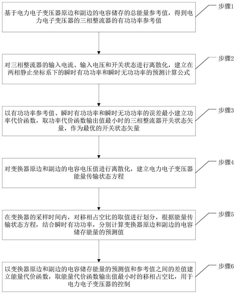
[0062] refer to figure 1 , which is a schematic flowchart of a two-stage DC bus coordinated control method for a power electronic transformer provided by the present invention, including specific steps.

[0063] Step 1, based on the total energy reference value stored in the capacitors of the primary and secondary sides of the power electronic transformer, the active power reference value of the three-phase rectifier of the power electronic transformer is obtained; the power electronic transformer includes a three-phase rectifier and a DC converter.

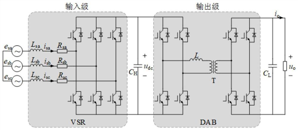
[0064] refer to figure 2 , which is a topological structure diagram of the power electronic transformer provided by the present invention.

[0065] In the embodiment of the present invention, the three-phase rectifier is a cascaded H bridge, and the DC converter is a dual active bridge.

[00...


PUM


Abstract

The invention discloses a two-stage direct current bus coordination control method and device for a power electronic transformer, and the method comprises the steps: carrying out the discretization of the capacitor voltage values of a primary side and a secondary side of a converter, and building an energy transmission state equation of the power electronic transformer; in the sampling time of the converter, dividing the value of the phase shift duty ratio, and calculating the predicted value of the capacitor storage energy of the converter according to the energy transmission state equation and the instantaneous active power; and establishing an energy cost function according to a difference value between a predicted value and a reference value of the capacitor storage energy, and taking a phase shift duty ratio when an output value of the energy cost function is minimum for controlling the power electronic transformer. By adopting the scheme, the control of the multi-section DC bus voltage is considered, the total energy storage amount is reasonably and dynamically distributed to the high-voltage side and the low-voltage side for common bearing, the problem that the high-voltage DC side voltage and the low-voltage DC side voltage fluctuate violently is solved, and meanwhile, the dynamic response speed of the system is high.

Description

technical field [0001] The invention relates to the technical field of power electronics, in particular to a method and device for the coordinated control of two-stage DC buses of power electronic transformers. Background technique [0002] Power electronic transformer (PET), as a key device in AC / DC hybrid grid, is highly controllable. Compared with traditional power frequency converters, PET has the advantages of small size and high power density, especially in the application of AC to DC, the advantages of PET are more significant. [0003] In terms of the control of the cascaded H-bridge (Cascaded H-bridge, CHB) and dual active bridge (Dual Active Bridge, DAB) two-stage power electronic transformer control, the solution adopted in the prior art is to combine the cascaded H-bridge The H-bridge and the dual-active bridge are regarded as two independent parts, so that they are respectively responsible for the control of the high-voltage and low-voltage DC bus voltages. The...

Claims


Application Information

Patent Timeline
Patent Type & Authority Applications(China)
IPC IPC(8): H02M7/219H02M3/335H02J3/32
CPCH02M7/219H02M3/3353H02J3/32
Inventor 孙毅超曹梓青李禹樊鄢寅宇
Owner NANJING NORMAL UNIVERSITY
Why Eureka
Try Eureka