Double-sided scraping device

A double-sided, scraping technology, applied in the field of daily sanitary ware, can solve the problems of non-continuous cleaning action, low glass wiping efficiency, and difficult to clean glass, etc., to improve the wiping effect, improve wiping efficiency, and save energy. good sex effect

Pending Publication Date: 2022-01-14
西安佳赢企业管理咨询有限公司
0 Cites 0 Cited by

AI-Extracted Technical Summary

Problems solved by technology

[0004] When using, the user needs to move the glass wiper in the direction of the wiper in front and the scraper in the back to clean the glass surface. When the glass wiper needs to switch directions during the moving process, the user needs to rotate the direction of the glass wiper to continue cleaning the glass in the opposite...

Method used

Above-mentioned mounting part 5 is the parts that are used to install the first scraping bar 3 and the second scraping bar 4, and mounting part 5 can be frame structure, plate-like structure or rod-like structure, also can be the parts of other structures, install The component 5 can be used to install the first scraping strip 3 and the second scraping strip 4 , and no specific structural limitation is made here. The mounting part 5 can be movably connected to the base 1 through a rotating connection or a sliding connection. After the installation component 5 is provided in this embodiment, the installation of the first scraping strip 3 and the second scraping strip 4 is more convenient.
In one embodiment, as shown in Figure 4, transmission part 21 can comprise: mounting base 21b, the transmission body 21c that is fixed on one end of mounting base 21b; Transmission body 21c stretches into limit hole 1a; Mounting base The end surface of 21b connected to the end of the transmission body 21c can be stuck outside the limiting hole 1a, and the first scraping strip 3 and the second scraping strip 4 are both connected to the base in transmission. In this embodiment, since the end surface of the mounting seat 21b can be stuck outside the limiting hole 1a, the transmission body 21c will not escape from the limiting hole 1a, and the structure of the wiper body 100 will be more stable and reasonable.
In one embodiment, the mounting part 5 can be provided with a first mounting groove 5b and a second mounting groove 5c; the first scraping strip 3 is installed in the first mounting groove 5b, and the second scraping strip 4 is installed in Inside the second installation groove 5c. In this way, the installation and disassembly of the first scraping strip 3 and the second scraping strip 4 are facilitated.
In one embodiment, the transmission part 21 can be a hollow structure, and the first magnet 22 can be fixed inside the transmission part 21, like this, both can play a protective role to the first magnet 22, and facilitate the first magnet 22 At the same time, the spatial structur...

Abstract

The invention discloses a double-sided scraping device, each scraping body comprises a base, a transmission assembly, a first scraping strip and a second scraping strip, the first scraping strip and the second scraping strip are arranged at an interval, the transmission assembly comprises a transmission part and a first magnet fixed on the transmission part, the first scraping strip and the second scraping strip are both in transmission connection with the transmission part, the first scraping strip and the second scraping strip are both movably connected with the base. According to the double-sided scraping device, the whole scraping process is continuous, operation is simpler and more convenient, the wiping efficiency of a user can be improved, wiping dead corners cannot be formed on the surface to be cleaned, and therefore the wiping effect can be improved.

Application Domain

Technology Topic

Image

  • Double-sided scraping device
  • Double-sided scraping device
  • Double-sided scraping device

Examples

  • Experimental program(1)

Example Embodiment

[0044]The technical solutions in the present application will be described below in conjunction with the drawings. Obviously, the described embodiments are merely the embodiments of the present invention, not all of the embodiments.
[0045] Hereinafter, the term "first", "second", etc. is for description purposes only, and cannot be understood as an indication or implies a relative importance or implicit a number of techniques indicated. Thus, features with "first", "second", and the like may be indicated or implicitly including one or more of this feature.
[0046] It will also be noted that in the present application embodiment, the same components or the same component are shown in the same reference numerals, and the same components in the present application, which may not be taken in one of the parts or components. The reference numerals should be understood that for other identical parts or components, reference numerals are equally applicable.
[0047] In the description of the present application, it is to be described in that, unless otherwise expressly specified and defined, the term "installation", "connected", "connection" should be broadly understood, for example, may be a fixed connection, or detachable Connect, or integrate; it can be mechanical connection, or may be electrically connected or can communicate with each other; may be directly connected, or by interminating indirectly, it can be an interaction between two components or two components. relation. For those skilled in the art, the specific meanings of the above terms can be understood in the present application according to the specific circumstances.
[0048] In the description of the present application, it is to be understood that the orientation or positional relationship of the indication of the term "upper", "lower", "side", "inside", "outside", etc. is based on the installation or positional relationship, only In order to facilitate the description of the present application and simplifying, not indicating or implying that the referred to, the device must have a specific orientation, and is constructed in a specific orientation, and thus is not to be understood as limiting the present application.
[0049] The embodiments of the present application provide a double-sided scraping device to improve the operation stability of the double-sided scraping device.
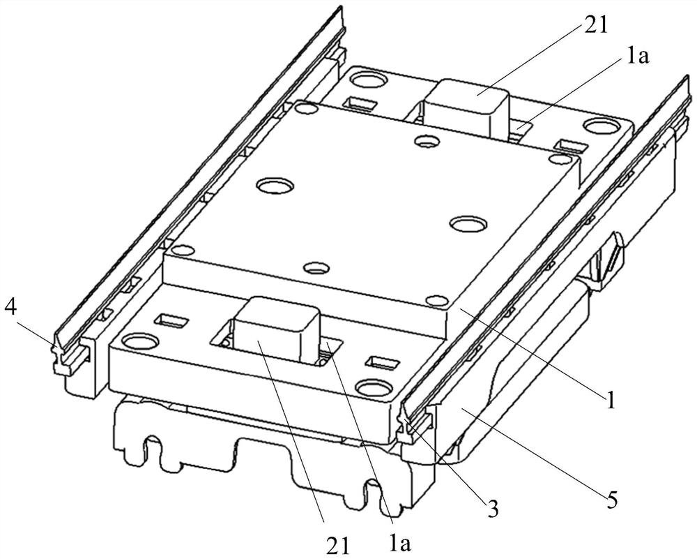
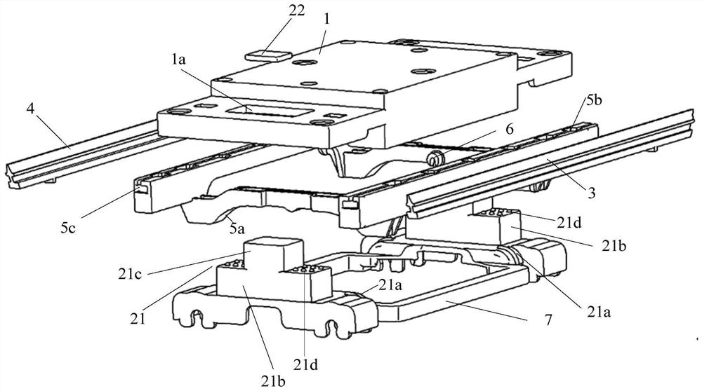
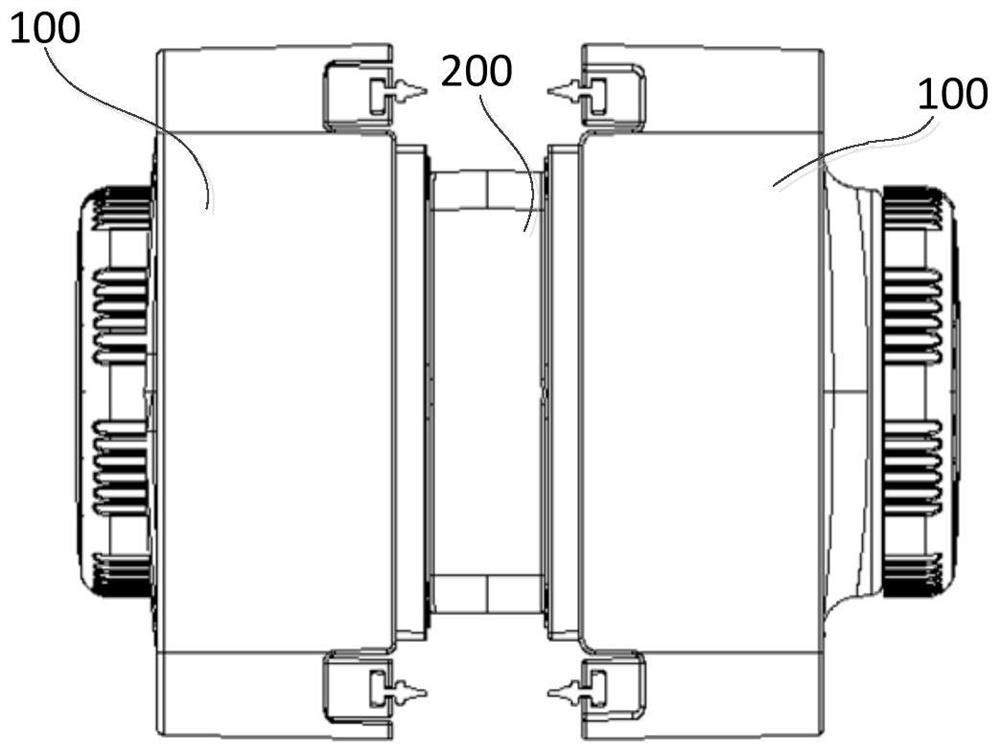
[0050] like image 3 As shown, the double-sided scraping device provided by the present application includes two ribbons 100, such as Figure 1-6 As shown, each of the respective body 100 includes a first scraper 3 and a second scraper 4 provided by a base 1, a transmission assembly, a second scraper 4, and a transmission assembly comprising a first magnet fixed to the transmission member 21. 22
[0051] When the two-wire body 100 is attached to the two opposing surfaces of the delay to be cleaned to scrape the surface of the cleaner, the first magazine 22 of one of the respective rubber 100 in the bodies 100 is another The first magnet 22 of the rubber 100 is attracted to each other, and the first magazine 22 of each of the respective body 100 is hysteresis, and the transmission member 21 is moved backward relative to the susceptor 1 to cause the transmission member 21 to drive the transmission member 21. The cutting direction is away from the surface of the to be cleaned without working, and the slips behind the travel direction are driven near the surface of the cleaner to be scratched.
[0052] In the present application, since the first magazine 22 of one of the respective fri body 100 in the double bodies 100 is attracted to each other, the first magnet 22 of each of the respective bodies 100 will be subject to another. The suction of the first magnet of the rubber and its own inertia, so that the movement of the first magnet 22 of each of the rubber 100 relative to the exercise of the susceptor 1 is lag.
[0053] The base 1 may be a plate-like structure, a frame-like structure, a housing structure, and the like, and the base 1 may be other structural forms. The base 1 can be used for other components of the mounting body 100, and the present application does not limit the specific structure of the susceptor 1.
[0054] The spacing distance between the first scraper 3 and the second scraper 4 may be any of 8 cm to 20 cm, and those skilled in the art can also use the first scraper 3 and the second scraper 4 in accordance with the placement. The interval distance is set to other distances, which is not specifically limited. The first scraper 3 is disposed between the second scraper 4, i.e., the first wiper 3 is not intersected between the second scraper 4.
[0055] In one embodiment, in order to make the structure of the rubber 100 more reasonable, the first scraping strip 3 and the second scraper 4 may be located on both sides opposite the base 1.
[0056] In one embodiment, the first scraping strip 3 and the second scraper 4 may be opposed, for example, the angle formed between the first scraper 3 and the second scraper 4 can be an acute angle. In order to make the double-sided scraping device structure more reasonable, the scratch efficiency is higher, and the first scraper 3 and the second scraper 4 can be parallel to parallel.
[0057] The drive member 21 may be a block structure, a plate-like structure, a housing structure, or may include any plurality of different components (gears, racks, cams, eccentric wheels, slides, belts, connectors, etc.), in different Connection relationship (abutment, hinge, sliding connection, gear-rack connection, belt connection, pin-chute connection, etc.) to each other, in this way, to achieve motion of the first magnet 22 to the first scraper 3 And the second scraper 4 to drive the first scraper 3 and the second scraper 4 for motion. The transmission member 21 can also be other structures that can be delivered with motion.
[0058] The first magnet 22 may be an ordinary magnet, or an electromagnet or other magnetic object, such as a magnetic material such as a wire block, a steel block. The first magnet 22 should have sufficient magnetic force to enable the first magnet 22 of one of the bodies 100 in the double ribbon 100 to stably attract each other with the first magnet 22 of the other of the other. In one embodiment, the two first magnets 22 of the double-sided scratching apparatus includes the polarity of the two first magnets 22 to enable the respective first magnets 22 of the double ribbed body 100 to each other. In another embodiment, the first magnet 22 of one of the two-sided bodies 100 includes a magnet, and the first magnet 22 of the other, the first magazine 22 of the other, can be iron, Steel or cobalt can be sucked by the magnet. The two first magnets 22 of the two of the two of the bodies 100 can be attracted to each other, and the present application does not limit the specific form.
[0059] Optional, such as image 3 As shown, the double-sided scraping apparatus may further include anti-absorbing gear 200, and the double ribbon is separated by the anti-suction isolation gear 200 to avoid the bobility of excessive absorption.
[0060] In the present application embodiment, the bodies 100 of the double-sided scratching device moves to scrape the surface of the cleaner, and may be the user manually moving the wiping body 100 to wipe cleaning the surface of the cleaning material, or an internal motor The drive flux body 100 is moved to scrape the cleaning surface, and the present application is not limited.
[0061] Alternatively, each of the wear bodies 100 may also include a walking assembly, including a walking motor and a travel wheel, such that each of the respective bodies 100 can be automatically driven without human drive.
[0062] Alternatively, each of the wear bodies 100 may be a glass robot that may include a sensor and an intelligent control system, such as a sensor and a smart control system, such as the wiping route, in addition to the above-described walking assembly.
[0063] The transmission member 21 drives the wiper on the front side of the travel direction away from the surface of the to be cleaned, and may be inside the front side of the front side of the travel direction, or other action form, such as folding, pushing down the front side of the travel direction. Wiper, etc., so that the cutting direction of the travel direction can be away from the surface of the deeper to be cleaned, so that the cutting direction is not scratched in the front side of the travel direction.
[0064] Accordingly, the transmission member 21 drives the squeezing of the rear side toward the surface of the row to be cleaned to perform scratching operation, which may be the surface of the cutting direction to the surface of the rear side to the surface of the cleaning material, or it can be in the form of an action. For example, a scraping on the rear side of the travel direction such that the cutting direction is adjacent to the surface of the rear side to be cleaned, so that the watery work can be performed. The operation of the scraping movement in the front side of the driving travel direction and the traveling direction is not specifically defined, as long as the switching of the wiper operation is capable of implementation.
[0065] The first scraper 3, the second scraper 4 can be rotated from the base 1 or slide to the base 1. The first scraper 3, the second scraper 4 can slide connection to the transmission member 21, rotate or securely connected. The first scraper 3, the second scraper 4 and the susceptor 1, and the transmission member 21 is not specifically defined herein. The first scraper 3, the second scraper 4 communicates with the transmission member 21, i.e., the transmission member can drive the first scraper 3 and the second scraper 4 for motion.
[0066] The first magnet 22 can be secured to the end of the transmission member 21, or may be secured to other positions of the transmission member 21, and the first magnet 22 of one of the respective rubber 100 in the bib bodies 100 can correspond to the other. One magnet 22 is attracted to each other, and the first magnet 22 is not limited to the specific mounting position of the first magnet 22 on the transmission member 21.
[0067] In one embodiment, the transmission member 21 can be a hollow structure, and the first magnet 22 can be fixed inside the transmission member 21, so that the first magnet 22 can be protected and facilitate the installation of the first magnet 22, At the same time, the spatial structure layout is also more reasonable, and the weight of the magnet is also small.
[0068] When the double-sided scraping device provided by the present application is scraped the surface of the cleaner, the first magnet 22 of each of the respective bodies 100 is subject to the suction of the first magnet 22 of the other, so that the first magnet 22 is The inertial force is hysteresis with the movement of the pedestal 1, and thereby passes through the blowing direction of the travel direction by the transmission member 21 to be collapsed without working, and the cutting direction of the travel direction is protruded from the rear side. Surface and scratch work. When the wicker 100 is moved to the edge of the surface to be cleaned, the rhinar body 100 can be directly controlled to the reverse direction. At this time, the first magnet 22 drives the first scraper by the transmission assembly under the action of the first magnet 22 hysteresis. The 3 and the second scraper 4 perform the switching of the working state, always enable the scraping strips on the front side of the travel direction without working, and the scraping strips behind the travel direction is extended.
[0069] It can be seen that the entire scraping process provided by the present application embodiment has a continuity, and it can be used to clean the surface like a blackboard, and the operation is easier to improve the user's wiping efficiency, and will not be cleaned Forming a wiping angle, thereby facilitating improving the wiping effect. Further, the double-sided scraping device provided by the present application can realize the switching of the first wiper strip 3 and the second scraper 4 in different travel directions of the junction body 100 by simple mechanical transmission. Due to the higher connection stability of mechanical transmission. The structural stability of each mechanical component is also higher, so that the stability of the rubber 100 is better, so that the structural stabilization of the double-sided scraping device is better. Further, the double-sided scraping device provided herein can achieve a double squeezing switch, and the energy saving is better.
[0070] In one embodiment, the distance between the first end of the first magnet 22 and the transmission member 21 is no more than the preset distance, wherein the first end is: when the wicker 100 is moved to scrape the surface of the cleaning. When the transmission member 21 is facing one end of the surface of the cleaner. The first preset distance can be any of from 0 to 10 mm. It will be appreciated that the first preset distance should be set to a smaller distance value such that the rubber 100 of the other surface of the cleaning material to be cleaned can produce suction. When the distance between the first magnet 22 and the first end of the transmission member 21 is, for example, the first magnet 22 is fixed to the first end of the transmission member 21, and the magnet 100 of the other surface of the other surface to be cleaned is cleaned. The larger the suction force generated by the first magnet 22, so that the probability of the first magnet 22 does not have a movement can be reduced, thereby reducing the probability that the blade does not switch when the direction of travel of the ribbon 100 is changed, and the work of the wiper 100 It is better to stabilize.
[0071] likeFigure 6-8 As shown in the present application embodiment, the outer surface of the susceptor 1 can be fixedly provided with a wipe 9 in order to wipe the surface of the cleaner. For example, the wipe 9 can be a wiping or sponge or the like.
[0072] like figure 2 As shown, the outer surface of the base 1 may form a stepped step, and the intermediate is protruded on both sides, so that after the wipe 9 is fixed to the outer surface of the susceptor 1, the wiping surface of the wipe 14 can be protruded in the intermediate 1 The outer surface of the part is parallel to each other, so that the user wipes the use.
[0073] In a specific embodiment, such as Image 6 As shown, in the free state, the scraping end of the first scraper 3 and the scraping end of the second scraper 3 may be slightly higher than the wiping surface of the wipe 14, so that when the wiper 100 is attached to the obtained matter When the surface, in the free state, the scraping end of the first scraper 3 and the second scraper 4 exists in the surface of the obtained matter to be cleaned, thereby reserves a certain activity space to the cutting.
[0074] like Figure 8 As shown, when the two-sided scratching device is moved to the B direction (i.e., the right side of the figure) to scrape the surface of the surface (not shown) (not shown), the first magnet 22 acts in its own inertia The lower phase is hysteresising for the movement of the pedestal 1, and the first magnet 22 is moved backwards (i.e., moving to the left), and further through the transmission member 21 inside the wiper body 100 (ie The scraping on the right side is retracted away from the surface of the tape cleaner, and does not perform wiper operation, and drives the squeegee in the rear side of the travel direction (ie, the left side of the blade) is protruded to be closed to clean the surface (this The scraping end of the squeegee on the rear side of the direction can be used to take the surface of the cleaner.
[0075] In one embodiment, if figure 1 , 2 As shown, each of the fruing bodies 100 may further include a mounting member 5; the mounting member 5 is active on the base 1, and the mounting member 5 is driven to the transmission member 21; the first scraper 3, the second scraper 4 The mounting member 5 is fixed to the mounting member 5; when the double ribbed body 100 is attached to the two opposing surfaces of the to be cleaned to scrape the surface of the cleaner, the first magnet 22 of each of the respective body 100 passes through the transmission. The component 21 drives the mounting member 5 to close to one end of the front side blade in the travel direction, away from the surface to be cleaned, and drive the mounting member 5 near the side of the rear side blade in the back side of the rear side cut to be cleaned.
[0076] The mounting member 5 is a member for mounting the first wiper strip 3 and the second scraper 4, and the mounting member 5 may be a frame structure, a plate-like structure or a rod-shaped structure, or a component of other structures, and the mounting member 5 can Used to install the first scraper 3 and the second scraper 4, this is not structurally defined herein. The mounting member 5 can be attached to the susceptor 1 by rotating the connection or sliding connection. In this embodiment, the mounting member 5 is provided, it is more convenient for the installation of the first scraper 3 and the second scraper 4.
[0077] In one embodiment, the mounting member 5 can be rotatably coupled to the base 1; the first scraper strip 3 and the second scraper 4 are located on both sides of the rotational centerline, respectively, the centerline of the mounting member 5 is relative to the base. When the seat is rotated; when the rhinar 100 is moved to scrape the surface of the cleaner, the first magnet 22 drives the mounting member 5 with respect to the base 1 to rotate, so that the rotation is mounted. 5 Keep approaching the front side of the front side cut from the surface to be cleaned, and the rotational mounting member 5 is adjacent the surface of the rear side blade near the back side of the rear squeezing. In a specific embodiment, the mounting member 5 can be rotated to the base 1 by the rotating shaft 6. For example, the middle portion of the mounting member 5 can be opened, and the hinge 6 can be fixed in the hinge hole, and a hinge can be provided on the inner surface of the base 1, and the rotating shaft 6 is attached to the hinge seat, and the shaft 6 can be hinged. Turn in the seat.
[0078] In the present embodiment, the mounting member 5 is rotatably coupled to the base 1, and the mounting member 5 can be easier to connect the mounting member 5, so that the structure of the rubber 100 is simpler.
[0079] In a specific embodiment, the distance between the first scraper 3 to the rotational centerline is equal to the distance from the second scraper 4 to the rotational centerline. Thus, the first scraper 3 can have the same lifting amplitude as the second scraper 4, so that the structure of the rubber 100 is more reasonable and is more convenient.
[0080] In one embodiment, if figure 2 , 5 As shown, the transmission member 21 may be provided with a first transmission structure 21a, and a second transmission structure 5a is provided on the mounting member 5, and the first transmission structure 21a is adapted to the second transmission structure 5a, and the first transmission structure 21a. The outer surface is slidable with the outer surface of the second transmission structure 5a. When the double ribbed is attached to the two opposing surfaces of the to be cleaned to clean the surface of the object to be cleaned, the first magnet 22 of each of the respective bodies passes the second transmission structure 5a by the first transmission structure 21a. The first transmission structure 21a is slid so that the mounting member 5 is adjacent to one end of the front side cutting direction away from the surface of the surface, and the mounting member 5 is adjacent to the surface of the rear side blade near the back side of the rear side.
[0081] In a specific embodiment, if figure 2 , 5 As shown, the outer surface of the first transmission structure 21a and the outer surface of the second transmission structure 5a may be an arc surface, and the arc surface of the first transmission structure 21a is slidably connected to the arc surface of the second transmission structure 5a. In this embodiment, the first transmission structure 21a is adapted to the shape of the second transmission structure 5a, and may be the arc surface of the first transmission structure 21a and the arc surface of the second transmission structure 5a. Specifically, the arc surface of the first transmission structure 21a may be a concave arc surface, the arc surface of the second transmission structure 5a is a convex surface; or the arc surface of the first transmission structure 21a is a convex surface, a second transmission structure. The curved surface of 5a is a concave curve.
[0082] In another embodiment, the outer surface of the first transmission structure 21a and the outer surface of the second transmission structure 5a may be a slope, and the slope of the first transmission structure 21a is slidable with the slope of the second transmission structure 5a.
[0083] In another embodiment, the transmission member 21 can be fixedly provided with a first drive rod, and a third arc-shaped structure may be provided on the mounting member 5, and the first drive lever is slidable with the third arc-shaped structure; when the wiper 100 is performed When moving to clean the surface of the to be cleaned, the first magnet 22 drives the third arc-shaped structure with respect to the first drive rod to slide with respect to the first drive rod, so that the mounting member 5 is adjacent to the front side of the front side cutting surface away from the side of the surface. Further, the mounting member 5 is adjacent to the surface of the rear side blade in the back side of the back side.
[0084] In other embodiments, the transmission member 21 can be fixedly provided with a fourth arc-shaped structure, and the mounting member 5 may be provided with a second drive rod, the second drive lever and the fourth arc-shaped structure; when the wicker 100 is moved When cleaning the surface of the cleaner, the first magnet 22 drives the second drive rod relative to the fourth arc-shaped structure by the fourth arc-shaped structure to keep the mounting member 5 near the front side of the front side cutting surface away from the surface of the surface, and The mounting member 5 is adjacent to the side of the rear side blade near the rear side cutting surface.
[0085] Both of the above three embodiments can cause the transmission member 21 to drive the mounting member 5 so that the mounting member 5 is adjacent to the front side cutting direction away from the front side cutting surface, and the mounting member 5 is close to the back side of the back side of the rear side blade. The surface of the cleaner, those skilled in the art can choose any of the above methods, or otherwise selecting the above effects.
[0086] Alternatively, the material of the first scraper 3 and the second scraper 4 can be plastic or rubber.
[0087] Alternatively, the shape of the first scraper 3 and the second scraper 4 may be curved, and the intermediate is protruding (i.e., ")" shape) ")") ")") ") water.
[0088] In one embodiment, if figure 1 , 2 As shown, the finisher 1a can be provided on the base 1; the transmission member 21 extends into the limit hole 1a, and the transmission member 21 can move on the first plane in the limit hole 1a, the first plane is: and the limit When the aperture 1a is perpendicular to the plane; when the wicker 100 is moved to scrape the surface of the cleaner, the first magnet 22 drives the transmission member 21 in the limit hole 1a.
[0089] The limiting hole 1a may be a through hole, or a blind hole, the cross-sectional shape of the limit hole 1a may be circular, rectangular, regular polygonal or irregular polygon, or other irregular graphics. The transmission member 21 can be moved on the first plane within the limit hole 1a, and it is understood that the cross-sectional profile of the portion of the transmission member 21 extends into the limit aperture 1a can be surrounded by the cross-sectional contour of the limit hole 1a. When the transmission member 21 is large, the cutting direction of the travel direction is subjected to a large thrust of the transmission member 21, and the present embodiment is provided on the base 1, and the motion range of the transmission member 21 can limit the movement range of the transmission member 21. Thus, the pressure and friction of the squeegee on the rear side of the travel direction derive the surface of the cleaner, and may reduce the probability of the transmission member 21 out of the susceptor 1, so that the structure 100 is more stable.
[0090] In one embodiment, if Figure 4 As shown, the transmission member 21 can include a mounting seat 21b, a transmission 21c fixed at one end end of the mount 21b; the transmission 21c extends into the limit hole 1a; the mount 21b is connected to the end surface of the transmission 21c at the end surface. Outside the bit hole 1a, the first scraper 3, and the second scraper 4 are connected to the base. In the present embodiment, since the end surface of the mounting seat 21b is caught in the limit hole 1a, the transmission of the drive body 21c does not take out the limit hole 1a, and the wiper 100 structure will be more stable and more reasonable.
[0091] In one embodiment, in order to reduce the friction of the mount 21b to reduce the damage of the base 1, the mounting seat 21b is connected to the end surface of the transmission body 21c can be provided with a surface smooth projection 21D. . The smooth projection 21d may be a circular projection, a semi-circular projection, a cubic convex, and the like.
[0092] In one embodiment, each of the fruing bodies 100 may further include a second magnet (not shown); the second magnet is fixed to the base 1; when the double-sided scraping device is in use, double body The second magnet of one of the respective rubber 100 is attracted to each other with the second magnet of the other of the other, so that the double ribbed body 100 is attached to the two opposite surfaces of the delay. The present application embodiment can be more securely adsorbed by the second magnet to be more securely adsorbed.
[0093] In one embodiment, if image 3 As shown, the frothy body 100 may include two transmission assemblies; two transmission assembly intervals. The transmission member 21 of the two of the transmission components is connected to the first scraper 3, and the second scraper 4 is driven; wherein the two of the transmission components 21 in the two transmission components are connected by the synchronization member 7. To achieve synchronous motion of the two transmission member 21. Specifically, the two transmission assemblies can be distributed in length directional intervals along the first wiper 3 or the second scraper 4. In a specific embodiment, the two transmission members 21 and the synchronizing member 7 are integrally formed structures. When the ribbon 100 includes two transmission assemblies, the first scraper 3 and the second scraper 4 can be larger, and the force is more uniform, more convenient for the first scraper 3 and the second scraper 4. Switch.
[0094] In one embodiment, the mounting member 5 may be provided with a first mounting groove 5b and a second mounting groove 5c; the first wiper strip 3 is mounted in the first mounting groove 5b, and the second scraper 4 is mounted in the second installation. The groove 5c is inserted. Thus, it is convenient for the installation and disassembly of the first scraper 3 and the second scraper 4.
[0095]In one embodiment, the mounting member 5 can be a frame structure; the mounting member 5 can include a transmission beam and a mounting beam, a transmission beam, and a mounting beam fixation; the transmission beam is transmitted from the transmission member 21, the first scraper 3. The second scraper 4 is mounted on the mounting beam.
[0096] In a specific embodiment, the mounting member 5 may be a "U" structure that is lifted at both ends and the intermediate decomposing. The two ends of the "U"-shaped structure warp may be fixed by the first mounting groove 5b, and the second mounting groove 5c is fixed to the first scraper 3, and the second scraper 4 is fixed.
[0097] In one embodiment, if Figure 7 As shown, each of the wear bodies 100 may further include a top cover 8, and the top cover 8 may include a top wall 81 and a side wall 82, and the side wall 82 is disposed about the circumferential direction of the top wall 81, and the top cover 8 can be fixed to the base. 1 Above, in this case, the inner hollow accommodating cavity can be formed, and the transmission assembly can be disposed within the receiving cavity.
[0098] In one embodiment, if Figure 7-9 As shown, each of the rubbers 100 may also include: a wipe 9, the wipe 9 is fixed to the base 1, and the wipe 9 is located between the first wiper strip 3 and the second scraper 4, when the bodies 100 are carried out When moving the surface of scratching the cleaner, the wipe 9 is in contact with the surface of the delay to wipe the surface.
[0099] In one embodiment, if Figure 6-9 As shown, any of the respective rubber 100 in the dual bodies 100 may further include a winding device 10, and the winding device 10 can be mounted on the top cover. When using, if the product is cleaned as a glass, the rubber 100 provided with the winding device 10 can be attached to the outside of the glass.
[0100] It will be appreciated that the above is meant to help meant the present application embodiments, and not to limit the scope of the present application embodiment. Those skilled in the art will apparently, various equivalents modified or variations may be made, or a combination of any of the above or any plurality of embodiments may be performed, or a combination of any of the various or any plurality of embodiments. Such modifications, variations, or combined schemes also fall within the scope of this application example.
[0101] It will also be appreciated that the description of the present application example focuses on emphasizing the differences between the various embodiments, and the same or similarity to each other can be referenced to each other, for the sake of brevity, here is not described herein.
[0102] It should also be understood that the configuration, case, category, and embodiments of the present application are intended for the convenience of the description, and should not constitute a particular defined, various methods, categories, situations, and the characteristics in the embodiments. In the case of a combination.
[0103] It will also be appreciated that in various embodiments of the present application, if there is no special description and a logical conflict, the terms and / or description of different embodiments have consistency, and can be referenced, technical features in different embodiments. A new embodiment can be combined according to its inherent logical relationship.
[0104] The above is only the specific embodiments of the present application, but the scope of the claims is not limited thereto, and any technicress, those skilled in the art, can easily think of change or replacement within the technical scope of the present application. It covers within the scope of protection of this application. Therefore, the scope of protection of the present application should be based on the scope of protection of the claim.

PUM

no PUM

Description & Claims & Application Information

We can also present the details of the Description, Claims and Application information to help users get a comprehensive understanding of the technical details of the patent, such as background art, summary of invention, brief description of drawings, description of embodiments, and other original content. On the other hand, users can also determine the specific scope of protection of the technology through the list of claims; as well as understand the changes in the life cycle of the technology with the presentation of the patent timeline. Login to view more.

Similar technology patents

Automation equipment for simulating tide motion of beach

ActiveCN101013532AConcise designSimple and efficient operationEducational modelsBiogeochemical cycleCoastal zone
Owner:NANJING UNIV

Classification and recommendation of technical efficacy words

  • Simple and efficient operation
  • Improve wiping efficiency

Battery case port wiping device

PendingCN110474014AImprove wiping efficiencyEasy to wipe operationCleaning using toolsCell component detailsEngineeringElectrical and Electronics engineering
Owner:DONGGUAN CHUANGMING BATTERY TECH

Ceramic chip surface wiper

InactiveCN113143136AEasy to wipeImprove wiping efficiencyCarpet cleanersFloor cleanersMechanical engineeringMaterials science
Owner:惠安严创优审科技有限公司

Quick blackboard wiping equipment for teaching equipment field

InactiveCN107244168AQuick and effective wipeImprove wiping efficiencyBoard cleaning devicesEngineeringWaste management
Owner:GUANGZHOU LINDIAN TECH CO LTD
Why Eureka
Try Eureka