
Motor variable frequency driver aging test device and test method thereof

A variable frequency drive, aging test technology, applied in the direction of measuring devices, measuring device shells, measuring electrical variables, etc., can solve the problems affecting the detection of motor variable frequency drives, inconvenient clamping and fixing of motor variable frequency drives, etc.

Pending Publication Date: 2022-01-14
浙江天毅半导体科技有限公司
View PDF6 Cites 0 Cited by
  • Summary
  • Abstract
  • Description
  • Claims
  • Application Information

AI Technical Summary

Problems solved by technology

[0004] The object of the present invention is to provide a motor variable frequency drive aging test device and its testing method, which has the advantage of being easy to use, and solves the problem that the existing motor variable frequency drive aging test device is inconvenient to test the aging test of the motor variable frequency drive. Clamp and fix the variable frequency drive of the motor with the same size, and adjust the load weight of the test motor, which affects the aging detection of the variable frequency drive of the motor under different load conditions

Method used


Image

  • Motor variable frequency driver aging test device and test method thereof
  • Motor variable frequency driver aging test device and test method thereof
  • Motor variable frequency driver aging test device and test method thereof

Examples


Embodiment Construction

[0026] The technical solutions in the embodiments of the present invention will be clearly and completely described below in conjunction with the embodiments of the present invention. Apparently, the described embodiments are only some, not all, embodiments of the present invention. Based on the embodiments of the present invention, all other embodiments obtained by persons of ordinary skill in the art without making creative efforts belong to the protection scope of the present invention.

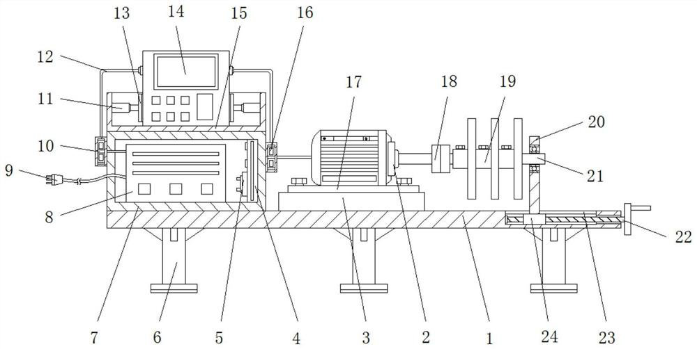
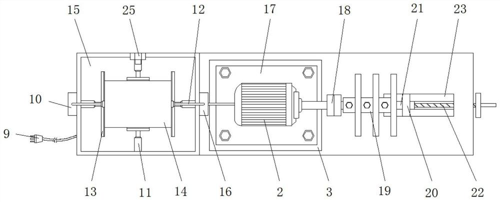
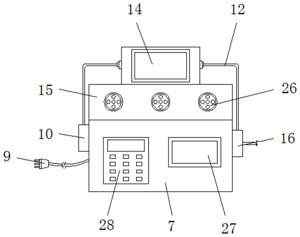
[0027] Base plate 1, load motor 2, fixed plate 3, central processing unit 4, communication module 5, outrigger 6, box body 7, transformer 8, power plug 9, first data acquisition module 10, electric telescopic rod 11 in the present invention , connection line 12, splint 13, variable frequency drive body 14, frame body 15, second data acquisition module 16, mounting plate 17, coupling 18, counterweight plate 19, vertical plate 20, rotating rod 21, threaded rod 22, Components such as threaded...


PUM


Abstract

The invention discloses a motor variable frequency driver aging test device and method, and the device comprises a bottom plate, the bottom of the bottom plate is fixedly connected with supporting legs, the left side of the top of the bottom plate is fixedly connected with a box body, the left side of the front surface of the box body is fixedly provided with a control panel, and the right side of the front surface of the box body is fixedly provided with a display. A central processing unit is fixedly installed on the right side of an inner cavity of the box body, a communication module is fixedly installed on the left side of the central processing unit, and a transformer is fixedly connected to the bottom of the inner cavity of the box body. The motor variable-frequency driver aging test device has the advantage of being convenient to use, and solves the problems that when an existing motor variable-frequency driver aging test device carries out aging test on a motor variable-frequency driver, motor variable-frequency drivers of different sizes are inconvenient to clamp and fix, the load weight of a tested motor is adjusted, and the motor variable-frequency driver aging test device is inconvenient to use. And the aging condition detection of the motor variable frequency driver under different load conditions is influenced.

Description

technical field [0001] The invention relates to the technical field of motor variable frequency drives, in particular to a motor variable frequency drive aging test device and a testing method thereof. Background technique [0002] The variable frequency drive is a power control device that uses frequency conversion technology and microelectronics technology to control the AC motor by changing the frequency of the motor's operating power supply. The variable frequency drive adjusts the voltage and frequency of the output power supply by switching off the internal IGBT, and provides the required power supply voltage according to the actual needs of the motor, thereby achieving the purpose of energy saving and speed regulation. In addition, there are many variable frequency drives. protection functions, such as overcurrent, overvoltage, overload protection, etc., with the continuous improvement of industrial automation, variable frequency drives have also been widely used. The...

Claims


Application Information

Patent Timeline
Patent Type & Authority Applications(China)
IPC IPC(8): G01R31/00G01R19/165G01R1/04G01J5/00
CPCG01R31/003G01R1/0408G01J5/0096G01R19/16571G01R19/16576
Inventor 何祖辉李志军邱秀华朱永斌
Owner 浙江天毅半导体科技有限公司
Learn More