
Medical radiography imaging system

A contrast imaging and imaging technology, which is applied in medical informatics, other medical devices, medical data mining, etc., can solve problems affecting the quality of contrast imaging, increasing workload, and negative effects that cannot be fed back.

Pending Publication Date: 2022-01-18
天津瑞好医疗科技有限公司
View PDF0 Cites 0 Cited by
  • Summary
  • Abstract
  • Description
  • Claims
  • Application Information

AI Technical Summary

Problems solved by technology

[0006] Second, the technician or nurse needs to manually input the injection parameters, which not only increases the workload and reduces the inspection efficiency, but also has the risk of input errors, and it is difficult to correct the wrong input;
[0007] Third, the injection dose of contrast medium is determined by technicians or nurses. If the dose is too low, it will affect the quality of contrast imaging, and if the dose is too high, it will cause unnecessary harm to the human body. high requirements;
[0008] Fourth, for example, the contrast agents of different inspection sites such as the brain, heart, liver, and lungs are quite different. General technicians or nurses do not have the ability to conduct medical research on different inspection sites. Appropriate injection parameters are a very difficult task;
[0009] Fifth, the injection of contrast agent (including different injection doses, injection flow rate) will have an impact on contrast imaging, but this impact, especially the negative impact, cannot be fed back to adjust and improve the injection plan;
[0010] Sixth, although it has been realized that the corresponding contrast agent injection plan needs to be adjusted according to the height of the individual patient, or the injection plan is given by the doctor, it is still necessary for the technician or nurse to manually input the corresponding parameters

Method used


Image

  • Medical radiography imaging system
  • Medical radiography imaging system
  • Medical radiography imaging system

Examples


Embodiment Construction

[0038] In order to enable those skilled in the art to better understand the solutions of the present invention, the following will clearly and completely describe the technical solutions in the embodiments of the present invention in conjunction with the drawings in the embodiments of the present invention. Obviously, the described embodiments are only It is an embodiment of a part of the present invention, but not all embodiments. Based on the embodiments of the present invention, all other embodiments obtained by persons of ordinary skill in the art without making creative efforts shall fall within the protection scope of the present invention.

[0039] It should be noted that the terms "first" and "second" in the description and claims of the present invention and the above drawings are used to distinguish similar objects, but not necessarily used to describe a specific sequence or sequence. It is to be understood that the data so used are interchangeable under appropriate ...


PUM


Abstract

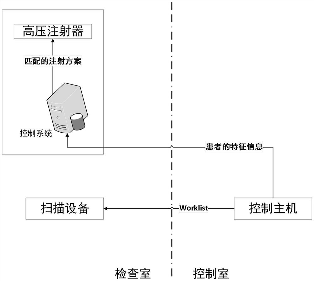
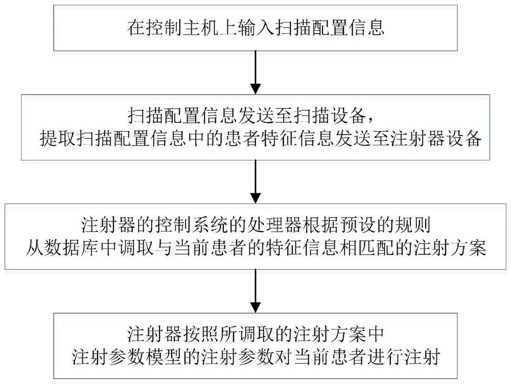
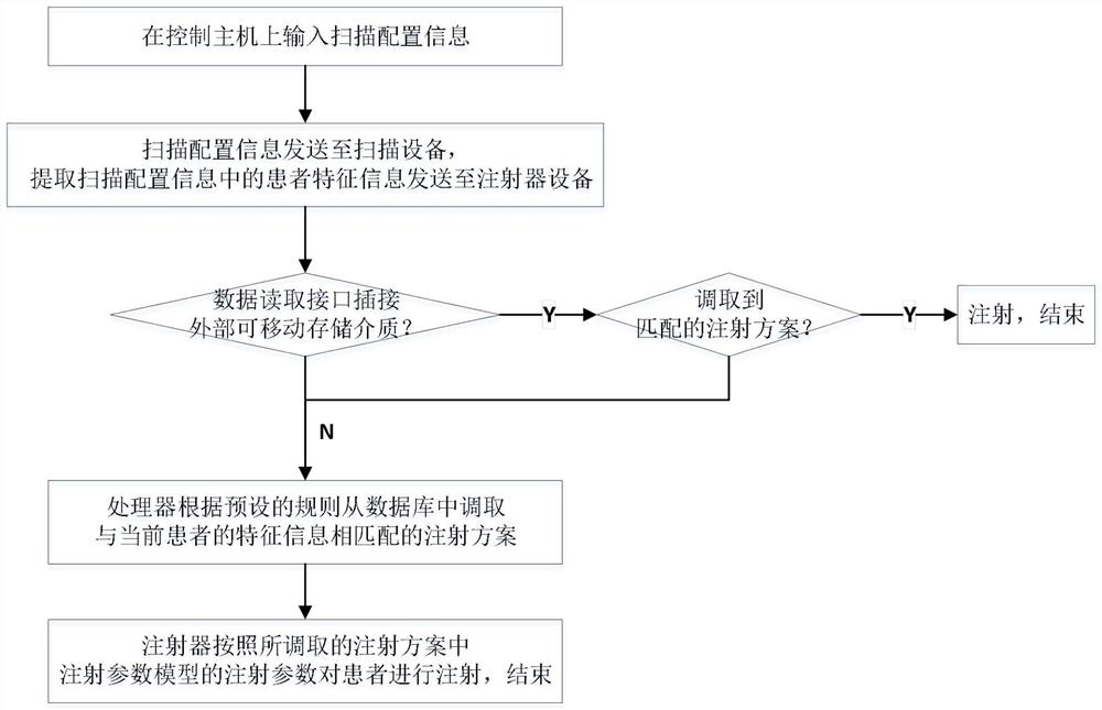
The invention discloses a medical radiography imaging system. The medical radiography imaging system comprises an injector device used for injecting a contrast agent, a scanning device for imaging and a control host used for inputting scanning configuration information corresponding to a patient to the scanning device, wherein the injector device is electrically connected with the control host through a signal transmission line, so that before, after or when the control host inputs the scanning configuration information to the scanning device, the injector device can be used for acquiring part of information in the scanning configuration information, and the part of information is attributive information of the patient, comprises an examination part, to be subjected to radiography, of the patient and further comprises any one or more of height, weight, gender, age, blood pressure, blood sugar and blood viscosity of the patient; and a matched injection scheme is called from a database according to the attributive information of the patient, and the injector device is used for preforming injecting on the patient according to injection parameters of the called injection scheme. According to the system, the workload of repeatedly inputting parameters by technicians or nurses can be effectively reduced, and an injection scheme can be intelligently matched.

Description

technical field [0001] The invention relates to the field of medical equipment, in particular to a medical contrast imaging system. Background technique [0002] The high-pressure injection system is a syringe used for contrast medium injection during contrast examination. By injecting contrast medium according to the set procedure, the contrast of the tissue can be enhanced, and the resolution of lesions and the accuracy of diagnosis can be improved. [0003] The operation steps of the existing syringe-based high-pressure injection system are: ① Install the syringe on the high-pressure injector; ② Insert one end of the drug suction tube into the front end of the syringe; ③ Insert the other end of the drug suction tube into the liquid medicine container; ④ Press the button to control the push rod of the high-pressure syringe to pull the syringe piston to suck the liquid medicine into the syringe; ⑤The system automatically judges whether there is residual air in the syringe a...

Claims


Application Information

Patent Timeline
IPC IPC(8): A61M5/00A61M5/142A61M5/20A61M5/48G06F16/2455G16H50/70
CPCA61M5/007A61M5/14216A61M5/20A61M5/484G16H50/70G06F16/2455A61M2005/14208A61M2205/35A61M2205/50A61M2205/3334A61M2205/3379
Inventor 张铁军王芳黄伟兰
Owner 天津瑞好医疗科技有限公司
Learn More