
Mechanical sealing interface fluid film forming measurement and control system

A technology of mechanical seal, measurement and control system, applied in the direction of engine seal, mechanical equipment, measuring device, etc., can solve the problem that the film formation state and thickness distribution of the interface fluid film cannot be adjusted in time, and the formation and integrity of the interface fluid film cannot be ensured. And other issues

Pending Publication Date: 2022-01-18
ZHEJIANG UNIV OF TECH
View PDF3 Cites 0 Cited by
  • Summary
  • Abstract
  • Description
  • Claims
  • Application Information

AI Technical Summary

Problems solved by technology

The above experimental devices have realized the test of the phase state change of the mechanical seal interface liquid film to a certain extent, but it is still unable to ensure the formation and integrity of the interface fluid film, let alone timely control the film formation state and thickness distribution of the interface fluid film Therefore, in order to better understand the film formation law, film shape and phase state change of the fluid film at the interface of the mechanical seal under different working conditions, a measurement and control system for the formation of the mechanical seal interface fluid film is developed. of great significance

Method used


Image

  • Mechanical sealing interface fluid film forming measurement and control system
  • Mechanical sealing interface fluid film forming measurement and control system
  • Mechanical sealing interface fluid film forming measurement and control system

Examples


Embodiment 1

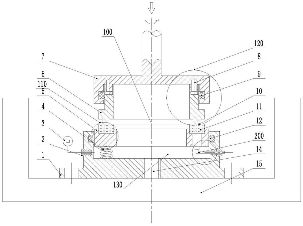
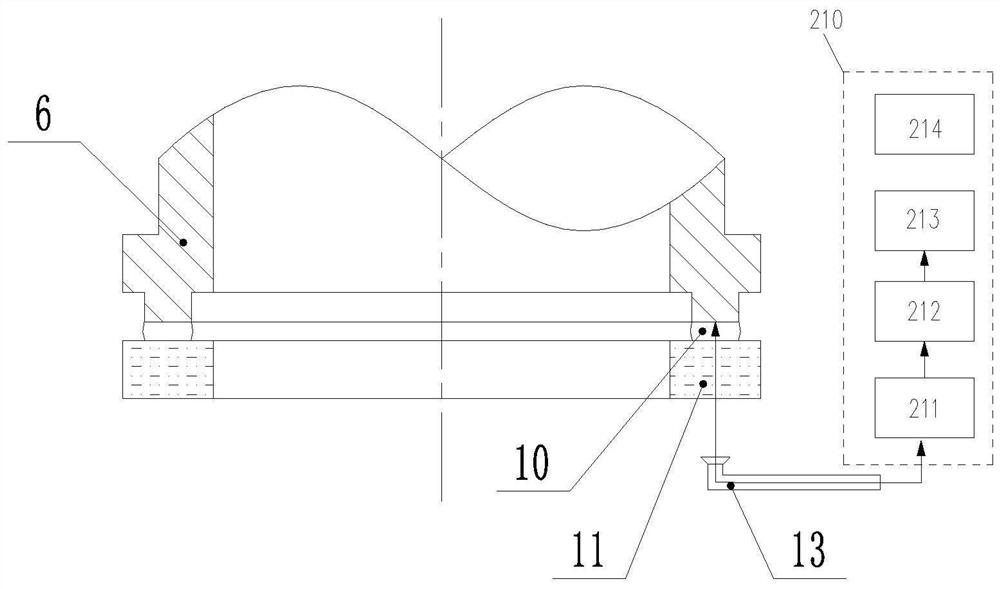
[0028] Embodiment 1 A mechanical seal interface fluid film forming measurement and control system, including a fluid container 15, a mechanical seal mechanism 100, and a liquid film forming measurement mechanism 200;

[0029] In the fluid container 15, a fluid lubricant containing nano-fluorescent powder is injected, and the top of the fluid container 15 is open, and a support 1 is fixed at the inner bottom; the top of the support 1 is provided with a sinking cavity, and the The bottom of the concave cavity is provided with a bottom threaded through hole 14; the side wall of the support 1 is provided with a plurality of support threaded holes 2a, and the support threaded holes 2a are arranged along the circumference of the support;

[0030] The mechanical seal mechanism 100 includes a matched static ring assembly 110 and a moving ring assembly 120. The static ring assembly 110 includes a static ring seat 5 and a static ring 11 installed in the static ring seat. The static ring ...


PUM


Abstract

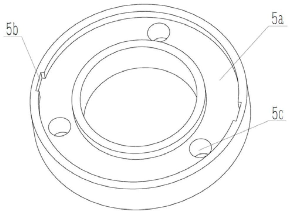
The invention discloses a mechanical sealing interface fluid film forming measurement and control system. The mechanical sealing interface fluid film forming measurement and control system comprises a fluid container, a mechanical sealing mechanism and a liquid film forming measurement mechanism, the mechanical sealing mechanism comprises a static ring assembly and a movable ring assembly, the static ring assembly comprises a static ring seat and a static ring arranged in the static ring seat, the static ring seat is arranged in a concave cavity in a sealing manner, an annular groove is formed in the top of the static ring seat, a plurality of step through holes are formed in the annular groove in the circumferential direction, the movable ring assembly is arranged right above the static ring assembly and comprises a movable ring top drive structure and a movable ring installed below the movable ring top drive structure, a fluid film is formed between a static ring sealing face and a movable ring sealing face, the liquid film forming measurement mechanism comprises an integrated device and a data processing device, a laser transmitter, an image collector, a fluid film transmitter and an image memory are integrated in the integrated device, and an image acquisition card, a data processor, an image analysis device and a fluid film thickness analysis testing device are arranged in the data processing device. The system has the beneficial effect that the film forming rule of the fluid film on the sealing interface is monitored in real time.

Description

technical field [0001] The invention relates to a measurement and control system for forming a fluid film at a mechanical seal interface, which is particularly suitable for a test and control device for forming a fluid film at a mechanical seal interface under different working conditions, and belongs to the field of mechanical seal performance testing and intelligent sealing. Background technique [0002] Mechanical seals are commonly used as shaft end seals for rotating machines in petroleum, petrochemical, chemical, electric power, pharmaceutical and aerospace industries. Their stable operating performance provides a reliable guarantee for the safe and stable operation of rotating machines. However, in the actual use process, the failure of mechanical seals is often difficult to predict. It is the goal of future mechanical seals to achieve measurement and control of operating performance and become an intelligent seal. At present, the parameters usually tested include end ...

Claims


Application Information

Patent Timeline
IPC IPC(8): F16J15/34F16J15/40G01N21/84
CPCF16J15/3492F16J15/3452F16J15/3464F16J15/40G01N21/8422
Inventor 彭旭东孟祥铠江锦波马艺
Owner ZHEJIANG UNIV OF TECH
Learn More