Electromechanical coupling flywheel kinetic energy recovery device for traffic vehicle

A kinetic energy recovery, electromechanical coupling technology, applied in the field of transportation, to achieve the effect of reducing loss, meeting high-power applications, and long life

Inactive Publication Date: 2013-06-05
SOUTHEAST UNIV
View PDF7 Cites 0 Cited by
  • Summary
  • Abstract
  • Description
  • Claims
  • Application Information

AI Technical Summary

Problems solved by technology

[0009]Technical problem: The present invention aims at the reliability, cost, efficiency and other problems of the traditional traffic vehicle kinetic energy recovery system, and provides a high-efficiency system suitable for all electric-driven vehicles. , long life, low cost electromechanical coupling flywheel kinetic energy recovery device for traffic vehicles

Method used


Image

  • Electromechanical coupling flywheel kinetic energy recovery device for traffic vehicle

Examples


Embodiment Construction

[0022] The present invention will be further described below in conjunction with the drawings.

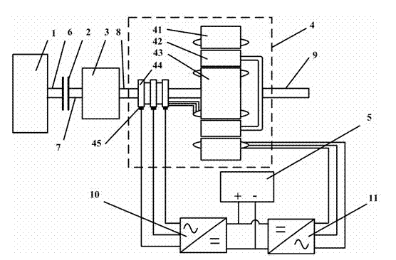
[0023] by figure 1 It can be seen that an electromechanical coupling vehicle flywheel kinetic energy recovery device includes a flywheel 1, a clutch 2, a transmission 3, a dual-rotor motor 4, a traction inverter unit 11, a flywheel inverter unit 10, a traction rectifier unit 5, flywheel Axle 6, transmission high speed shaft 7 and load output shaft 9. The dual-rotor motor 4 includes transmission low speed shaft 8, slip ring 44, brush 45, inner rotor 43, outer rotor 42 surrounding said inner rotor 43, and surrounding The stator 41 of the outer rotor 42, the slip ring 44 is arranged on the transmission low-speed shaft 8, the brush 45 is in contact with the slip ring 44, and the stator 41 and the inner rotor 43 are both provided with polyphase windings; The flywheel 1 is connected to the clutch 2 through the flywheel shaft 6, the clutch 2 is connected to the transmission 3 through the t...


PUM


Abstract

The invention relates to an electromechanical coupling flywheel kinetic energy recovery device for a traffic vehicle, which comprises a flywheel, a clutch, a transmission, a double-rotor motor, a traction rectifying unit, a traction inverter unit, a flywheel inverter unit, a flywheel shaft, a transmission high-speed shaft, a transmission low-speed shaft and a load output shaft. The double-rotor motor comprises the transmission low-speed shaft, a slip ring, an electric brush, an inner rotor, an outer rotor surrounding the inner rotor and a stator surrounding the outer rotor. The slip ring is arranged on the transmission low-speed shaft. The electric brush is in contact with the slip ring. Both the stator and the inner rotor are provided with multiphase windings. The flywheel is connected with the clutch through the flywheel shaft. The clutch is connected with the transmission through the transmission high-speed shaft. The transmission is connected with the inner rotor through the transmission low-speed shaft. The outer rotor is connected with the load output shaft. In the invention, the double-rotor motor is used as the core, kinetic energy is transferred back and forth between theflywheel and a load by the electromechanical coupling between the inner and outer rotors and the stator, the loss is low, and the overall efficiency is high.

Description

technical field [0001] The invention belongs to the technical field of traffic, and in particular relates to a kinetic energy recovery system for traffic vehicles. Background technique [0002] Now, traffic vehicles all over the world are facing the contradiction between industrial development and environmental protection. Energy issues and carbon dioxide emissions are problems that need to be solved immediately. People urgently need high-efficiency environmental protection technologies to ensure the sustainable development of the automobile industry and rail transit vehicles. At present, most vehicles use the frictional resistance generated by the braking system to achieve deceleration or parking. When the vehicle brakes, the kinetic energy of the vehicle is converted into heat energy on the brake and is lost in vain. Traffic vehicles generally work frequently in deceleration. , Parking, starting, and afterburning states are particularly prominent in urban rail transit veh...

Claims


Application Information

Patent Timeline
Patent Type & Authority Patents(China)
IPC IPC(8): B60K17/26B60K17/12B60K25/00
Inventor 张建忠程明
Owner SOUTHEAST UNIV
Why Eureka
Try Eureka