
Electronic device

An electronic device and terminal technology, which is applied in the direction of electrical digital data processing, digital processing power distribution, instruments, etc., can solve the problems of graphics card temperature rise, frequency reduction, and heat dissipation mechanism cannot function, and achieve the effect of avoiding frequency reduction

Pending Publication Date: 2022-01-18
GIGA BYTE TECH CO LTD
View PDF2 Cites 0 Cited by
  • Summary
  • Abstract
  • Description
  • Claims
  • Application Information

AI Technical Summary

Problems solved by technology

However, the existing graphics card will cause the problem that its heat dissipation mechanism is difficult to play an effective role in some usage scenarios
For example, in a server, the components will be configured very compactly to maximize the utilization of the limited space, so the slots of the graphics cards are inevitably arranged at short intervals, which will make it difficult to install multiple cards at the same time. When the graphics card is used, there is not enough space between the graphics cards for air intake, which seriously reduces the cooling air flow through the graphics card. As a result, the heat dissipation mechanism cannot function, causing the graphics card to heat up and cause frequency reduction.

Method used


Image

  • Electronic device
  • Electronic device
  • Electronic device

Examples


Embodiment Construction

[0058] The detailed features and advantages of the present invention are described in detail below in the embodiments, the content of which is sufficient to enable anyone familiar with the relevant art to understand the technical content of the present invention and implement it accordingly, and according to the content, claims and drawings provided in this specification , anyone familiar with the related art can easily understand the related objects and advantages of the present invention. The following examples further illustrate the concept of the present invention in detail, but do not limit the scope of the present invention in any way.

[0059] In addition, for the purpose of tidy drawings, some known and commonly used structures and elements may be represented in a simple schematic manner in the drawings. Among them, some features in the drawings of this case may be slightly enlarged or their proportions or dimensions may be changed to facilitate understanding and viewi...


PUM


Abstract

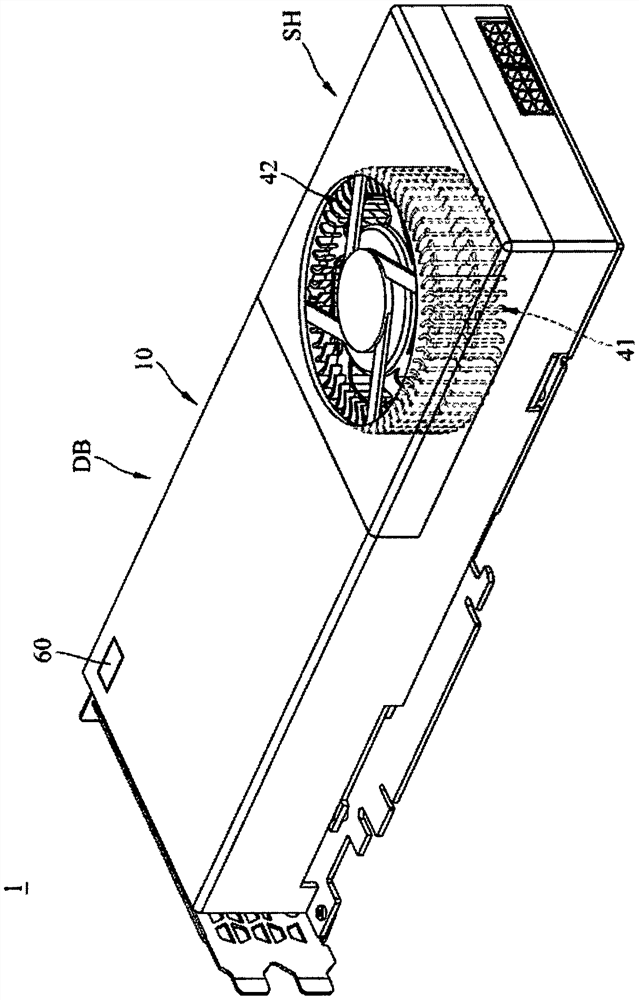
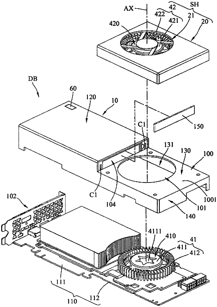
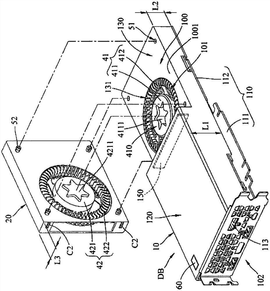
The invention relates to an electronic device which comprises a device body. The device body comprises a plate body, a first shell and a first fan. The plate body is provided with a first area and a second area. The first shell comprises a first plate part, a second plate part and an end plate part; and an air outlet area is formed between the first plate part and the first area. The air outlet area is opposite to the end plate part. The first housing forms a recessed portion on the second plate portion. The recessed portion is directly connected to the end plate portion and has a recessed bottom surface extending to the end plate portion. The second plate part is provided with an air inlet area which is positioned on the bottom surface of the recess and corresponds to the second area; and the first fan is arranged between the second area and the second plate part and corresponds to the air inlet area.

Description

technical field [0001] The present invention relates to an electronic device, especially an electronic device with a fan. Background technique [0002] A graphics card is mainly used to convert the display information required by the computer system to drive the display. With the rapid development of industries such as gaming, graphics, or multimedia production, more and more high-spec graphics cards that can display high-quality images smoothly and efficiently handle complex graphics operations are appearing on the market. [0003] In order for graphics cards to operate at standard operating temperatures, some graphics cards are equipped with an air-cooled heat dissipation mechanism that includes one or more fans to remove heat by directing airflow through the graphics card. However, the existing graphics card may cause the problem that its heat dissipation mechanism is difficult to perform effectively in some usage scenarios. For example, in a server, the components will...

Claims


Application Information

Patent Timeline
Patent Type & Authority Applications(China)
IPC IPC(8): G06F1/20G06F1/18
CPCG06F1/20G06F1/206G06F1/181G06F1/185
Inventor 黄顺治毛黛娟郭春亮
Owner GIGA BYTE TECH CO LTD
Learn More