Machining equipment for metal parts of automatic equipment
A technology of metal parts and processing equipment, which is applied in the field of automatic equipment parts processing, and can solve problems such as complex structure, affecting plastic effect, and low processing accuracy
- Summary
- Abstract
- Description
- Claims
- Application Information
AI Technical Summary
Problems solved by technology
Method used
Image
Examples
Embodiment 1
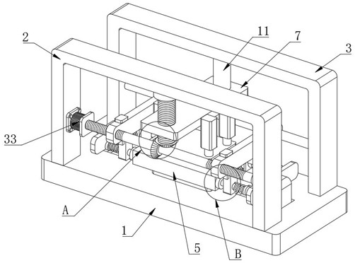
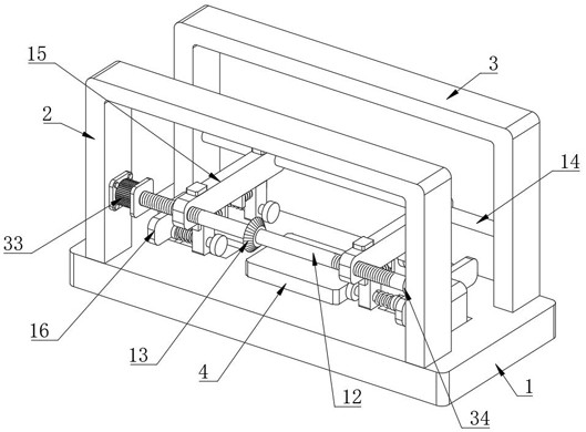
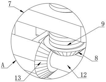
[0031] like Figure 1 to Figure 8 As shown, a processing equipment for automatic equipment metal parts includes a workbench 1, the top of the workbench 1 is fixedly connected with a first support frame 2 and a second support frame 3, and the top of the workbench 1 is fixedly connected with a supporting plate 4, The top of the supporting plate 4 is provided with a workpiece 5, the top of the workpiece 5 is provided with a pressing plate 6, the top of the pressing plate 6 is provided with a first movable plate 7, and the bottom of the first movable plate 7 is provided with a first bevel gear 8. The top of a bevel gear 8 is fixedly connected with the first threaded column 9, the first threaded column 9 runs through the first movable plate 7, the connection mode between the first threaded column 9 and the first movable plate 7 is threaded connection, the first threaded column The top of 9 is connected with the first support frame 2 through the first bearing 10, the second support ...
Embodiment 2
[0034] see Figure 1 to Figure 8 , where the same or corresponding components as those in Embodiment 1 use the corresponding reference numerals as in Embodiment 1, and for the sake of simplicity, only the differences from Embodiment 1 will be described below. The difference between this embodiment 2 and embodiment 1 is: please refer to figure 1 , figure 2 , Figure 4 and Figure 7 , the elastic correction unit includes a clamping plate 17 arranged on one side of the second movable plate 18, and one side of the clamping plate 17 is fixedly connected with a first fixed column 19, and the first fixed column 19 runs through the second movable plate 18, and the first fixed column 19 passes through the second movable plate 18. One end of the fixed column 19 away from the clamping plate 17 is fixedly connected with a fixed plate 20, the outside of the first fixed column 19 is provided with a tension spring 21, and the two ends of the tension spring 21 are connected to the fixed p...
Embodiment 3
[0036] see Figure 1 to Figure 8 , where the same or corresponding components as those in Embodiment 1 use the corresponding reference numerals as in Embodiment 1, and for the sake of simplicity, only the differences from Embodiment 1 will be described below. The difference between this embodiment 3 and embodiment 1 is: please refer to figure 1 , Figure 4 and Figure 7 , the movable limit mechanism includes a first fixed plate 24 arranged on one side of the second movable plate 18, the top of the first fixed plate 24 is fixedly connected with the bottom of the movable push plate 15, the first fixed plate 24 and the second movable plate 18 Connected by the first compression spring 25, the bottom of the movable push plate 15 is provided with a chute 22, the first slide block 23 is provided in the chute 22, the first slide block 23 is fixedly connected with the second movable plate 18, the chute 22 The top inner wall is provided with a first rectangular hole 26, the top of th...
PUM
 Abstract
Description
Claims
Application Information
 - R&D
- Intellectual Property
- Life Sciences
- Materials
- Tech Scout
- Unparalleled Data Quality
- Higher Quality Content
- 60% Fewer Hallucinations
Browse by: Latest US Patents, China's latest patents, Technical Efficacy Thesaurus, Application Domain, Technology Topic, Popular Technical Reports.
© 2025 PatSnap. All rights reserved.Legal|Privacy policy|Modern Slavery Act Transparency Statement|Sitemap|About US| Contact US: help@patsnap.com


