
A fiber coupler for high-efficiency coupling of high-power pump light

A fiber optic coupler and pumping optical fiber technology, applied in the field of fiber optic couplers, can solve the problems of difficult fiber coupling, low optical power into the fiber, and low pumping efficiency, and achieve low difficulty in processing and adjustment, high coupling efficiency, The effect of high fiber insertion efficiency

Inactive Publication Date: 2011-12-28
TSINGHUA UNIV
View PDF0 Cites 0 Cited by
  • Summary
  • Abstract
  • Description
  • Claims
  • Application Information

AI Technical Summary

Problems solved by technology

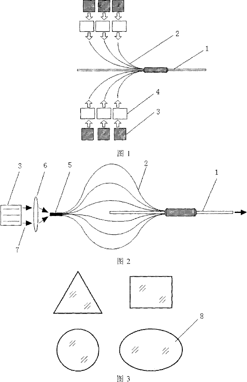
[0005] The purpose of the present invention is to propose a fiber coupler that realizes high-efficiency coupling of high-power pump light. Since the multi-branch pump fiber has only one fiber input end, it overcomes the problems of complex structure and difficult installation and adjustment in the prior art. Disadvantages: Since the shape of the fiber input end can be any shape such as rectangle, ellipse, circle, triangle, etc., there is no need for a complex shaping coupling system, and it can be directly matched with various forms of laser pump sources, and the fiber entry efficiency is high, so It overcomes the disadvantages of low pumping efficiency, low optical power into the fiber, and difficult coupling between the laser pump source and a single small-diameter pump fiber in the prior art.

Method used


Image

  • A fiber coupler for high-efficiency coupling of high-power pump light
  • A fiber coupler for high-efficiency coupling of high-power pump light
  • A fiber coupler for high-efficiency coupling of high-power pump light

Examples


Embodiment Construction

[0015] The detailed structure of the present invention will be described below in conjunction with the accompanying drawings.

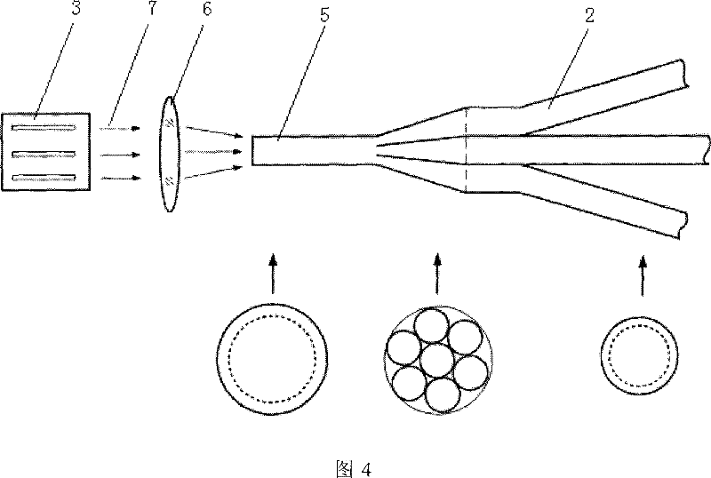
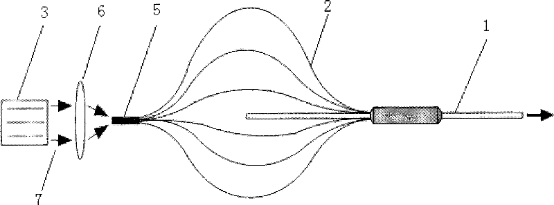
[0016] The structure of the first embodiment of the present invention is as figure 2 As shown, in the application of using a fiber coupler to pump a fiber laser, the pump light (7) emitted by the laser pump source (3) directly enters the fiber input of the fiber coupler through the action of the optical coupling component (6). end (5), and then through the multi-branch pumping fiber (2) transmission respectively, the output end of the pumping fiber (2) is injected into the main fiber (1) of the fiber coupler, and the pumping light (7) is in The inside of the main fiber (1) is transmitted along a certain direction, and finally a pumping beam with high beam quality is obtained at one end of the main fiber (1), which is used to pump the fiber laser.

[0017] A fiber coupler for high-efficiency coupling of high-power pump light proposed by the present i...


PUM


Abstract

The invention relates to an optical fiber coupler for realizing high-efficiency coupling of high-power pump light, and belongs to the technical field of optics and laser optoelectronics. Its characteristic is that in the application of using fiber coupler to pump fiber laser, the pump light emitted by the laser pump source passes through the action of optical coupling components, directly enters the fiber input end of the fiber coupler, and then passes through the multi-branch The transmission of the pump fiber is injected into the main fiber of the fiber coupler at the output end of the pump fiber. The pump light is transmitted along a certain direction inside the main fiber, and finally output at one end of the main fiber for pumping the fiber laser. Since the multi-branch pumping fiber of the fiber coupler proposed by the present invention has only one fiber input end, and because the end face shape of the fiber input end can be arbitrary, it does not need a complex shaping coupling system, and can be directly connected to various forms of The laser pump source is matched, and the fiber insertion efficiency is high, which avoids the complex optical shaping system.

Description

technical field [0001] The invention relates to an optical fiber coupler, which belongs to the technical field of optics and laser optoelectronics. Background technique [0002] Fiber lasers have attracted widespread attention due to their high efficiency, low threshold, high beam quality, compactness, and high performance / price ratio, and have been developed by leaps and bounds. In recent years, due to the maturity of high-power pump source technology and the application of cladding pump technology, the output power of fiber lasers and fiber amplifiers has been significantly improved, showing broad application prospects in military, medical and industrial processing fields. [0003] At present, the most critical issue limiting the increase in the output power of double-clad fiber lasers is how to obtain more pump power from the gain fiber, so improving the pump coupling method between the pump source and the fiber and increasing the optical power into the fiber has become a...

Claims


Application Information

Patent Timeline
Patent Type & Authority Patents(China)
IPC IPC(8): G02B6/42G02B6/26
Inventor 巩马理黄磊殷树鹏柳强闫平李晨
Owner TSINGHUA UNIV
Learn More