Electrolytic bath for electroplating

An electrolytic cell and cell body technology, applied in the plating tank, electrolytic process, electrolytic components, etc., can solve the problems of accumulation of large impurities at the corners, easy accumulation of impurities at the corners, affecting the electroplating effect, etc., to reduce corrosion damage and ensure use. Longevity, the effect of prolonging the lifespan

Pending Publication Date: 2022-01-21
仇泽金
View PDF1 Cites 1 Cited by
  • Summary
  • Abstract
  • Description
  • Claims
  • Application Information

AI Technical Summary

Problems solved by technology

[0004] Although the above comparative patent can scrape off the impurities on the side wall of the main mechanism, and can use a brush to clean the inner surface of the bottom end of the main mechanism, and use a shovel to remove the impurities cleaned by the scraper and the brush, but in the process of cleaning the main mechanism When cleaning the inside, only the impurities attached to the inner sides can be cleaned, while the other inner surface sides cannot be cleaned of impurities, and the impurities continue to accumulate on the other sides. After long-term use, the accumulated impurities will affect the effect of electroplating. Electrolyzer The corners inside are easy to accumulate impurities, and the existing technology cannot effectively clean the corners. After a long period of use, a large amount of impurities will accumulate at the corners, which will affect the effect of electroplating.

Method used


Image

  • Electrolytic bath for electroplating
  • Electrolytic bath for electroplating
  • Electrolytic bath for electroplating

Examples


Embodiment Construction

[0031] The following will clearly and completely describe the technical solutions in the embodiments of the present invention with reference to the accompanying drawings in the embodiments of the present invention. Obviously, the described embodiments are only some, not all, embodiments of the present invention. Based on the embodiments of the present invention, all other embodiments obtained by persons of ordinary skill in the art without making creative efforts belong to the protection scope of the present invention.

[0032] In describing the present invention, it is to be understood that the terms "center", "longitudinal", "transverse", "length", "width", "thickness", "upper", "lower", "front", " Back", "Left", "Right", "Vertical", "Horizontal", "Top", "Bottom", "Inner", "Outer", "Clockwise", "Counterclockwise", etc. or The positional relationship is based on the orientation or positional relationship shown in the drawings, which is only for the convenience of describing t...


PUM


Abstract

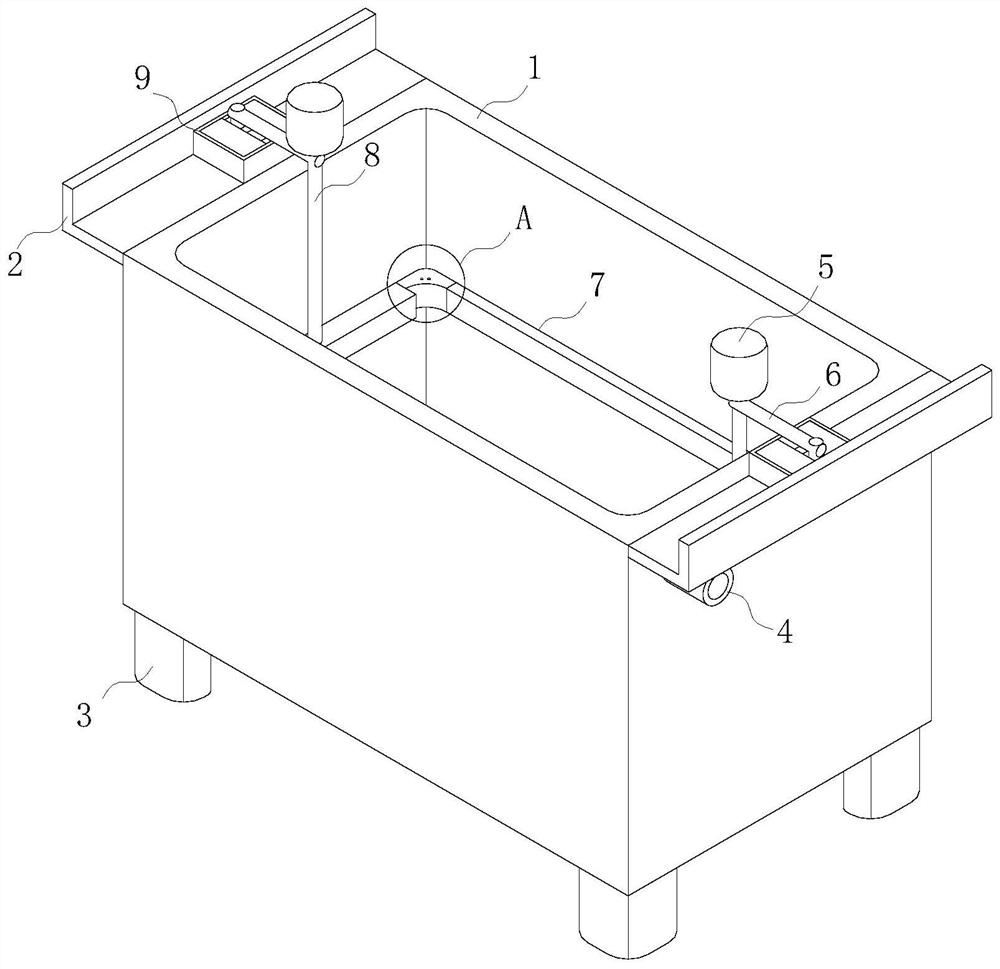
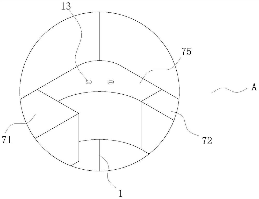
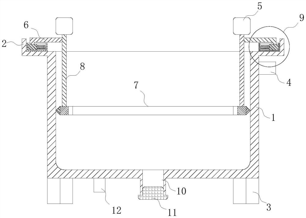
The invention discloses an electrolytic bath for electroplating. The electrolytic bath for electroplating comprises a bath body, foot supports are fixedly connected to the positions, close to the edges of the four corners, of the outer surface of the lower end of the bath body, fixing plates are symmetrically and fixedly connected to the positions, close to the edges of the upper end, of the outer surfaces of the left side and the right side of the bath body, protection mechanisms are fixedly connected to the middle positions of the upper surfaces of the two fixing plates, supporting rods are fixedly connected to the middle positions of the upper ends of the protection mechanisms, telescopic rods are fixedly connected to one ends of the supporting rods, a hydraulic pump is fixedly installed at the upper ends of the telescopic rods, and an inner surface cleaning mechanism is fixedly connected to the lower end of the telescopic rod. According to the electrolytic bath, impurities attached to the side faces of all the inner surfaces of the electrolytic bath can be cleared by arranging the inner surface cleaning mechanism, and thus the situation that the impurities are continuously accumulated on other side faces to affect the electroplating effect is avoided; and the impurities at the corners are cleared by arranging a corner cleaning mechanism, and thus the impurities at the corners can be effectively cleared through the corner cleaning mechanism.

Description

technical field [0001] The invention relates to the technical field of electroplating equipment, in particular to an electrolytic tank for electroplating. Background technique [0002] The electrolytic cell is composed of a cell body, an anode and a cathode, most of which are separated by a diaphragm from the anode chamber to the cathode chamber. According to the different electrolytes, it is divided into three types: aqueous solution electrolyzer, molten salt electrolyzer and non-aqueous solution electrolyzer. When direct current passes through the electrolytic cell, an oxidation reaction occurs at the interface between the anode and the solution, and a reduction reaction occurs at the interface between the cathode and the solution to produce the desired product. Optimizing the design of the electrolytic cell structure and rational selection of electrode and diaphragm materials are the key to improving current efficiency, reducing cell voltage, and saving energy consumptio...

Claims


Application Information

Patent Timeline
Patent Type & Authority Applications(China)
IPC IPC(8): C25D17/00C25D17/02C25D21/00B08B9/087
CPCC25D17/00C25D17/02C25D21/00B08B9/087
Inventor 仇泽金孙奥
Owner 仇泽金
Why Eureka
Try Eureka