Construction method for prefabricated box girder support in complex city environment

A construction method and box girder technology, applied in the direction of bridges, bridge construction, erection/assembly of bridges, etc., can solve the problems of harsh working environment, weld corrosion, plate cracking, etc., to improve efficiency, save costs, and ensure safety. Effect

Pending Publication Date: 2022-01-21
中能建建筑集团有限公司
View PDF5 Cites 5 Cited by
  • Summary
  • Abstract
  • Description
  • Claims
  • Application Information

AI Technical Summary

Problems solved by technology

Bridge erecting machines are widely used in bridge erection construction. The operating environment is harsh, frequent transition operations, weld corrosion, plate cracking and other damage occur from time to time, which can easily lead to major safety accidents

Method used


Image

  • Construction method for prefabricated box girder support in complex city environment
  • Construction method for prefabricated box girder support in complex city environment
  • Construction method for prefabricated box girder support in complex city environment

Examples


Embodiment 1

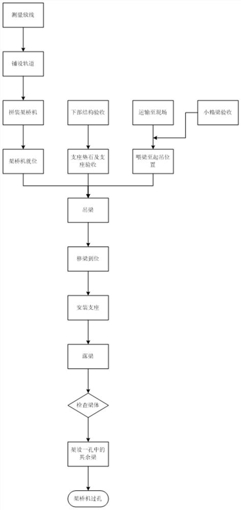
[0097] S1, measurement and setting out;

[0098] S11. Check the elevation and plane position of the supporting structure

[0099] Before erecting and installing the box girder, use instruments to check the elevation and plane position of the supporting structure. When checking, draw the mounting axis and end line on the supporting structure so that the box girder can be positioned accurately.

[0100] S12, pay-off and control position

[0101] According to the actual line centerline and pier center mileage released, the longitudinal centerline of each hole beam, the vertical and horizontal centerline of the support, the horizontal line of the plate end position and the contour line of the bottom of the support are released on the pier abutment surface, and the horizontal line of the plate end position Set out the bottom edge point of each box girder.

[0102] S2. Laying track and assembling bridge erecting machine;

[0103] S21. Selection of bridge erecting machine assembly...

Embodiment 2

[0158] Erection of ramp box girder

[0159] Since the ramp bridge deck is narrow and the longitudinal slope exceeds the design capability of the bridge erecting machine (the longitudinal slope does not exceed 3% slope ratio), necessary technical measures must be taken to erect the ramp box girder to ensure the safety of the erection.

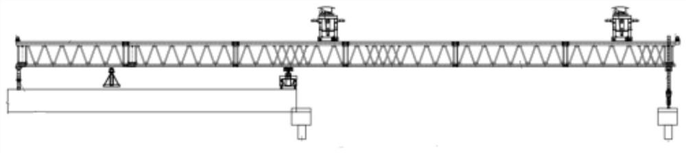
[0160] (1) Transformation of the bridge erecting machine

[0161] In order to adapt to the longitudinal slope with a slope ratio of 5.5%, it is necessary to modify the length of the front, middle and rear outriggers and the rear support of the bridge erecting machine to keep the bridge erecting machine in a stable posture parallel to the ground during erection. Considering that the rear of the bridge erecting machine is the main body of the load, adjusting the rear has little influence on the stability of the bridge erecting machine.

[0162] Therefore, the modification of the bridge erecting machine mainly adopts to increase the length of the mi...


PUM


Abstract

The invention discloses a construction method for a prefabricated box girder support in a complex city environment, and belongs to the technical field of bridge engineering, and the construction method comprises the following steps: S1, carrying out surveying and setting out; S2, laying tracks, and assembling a bridge girder erection machine; S3, enabling the bridge girder erection machine to erect the box girder in a high-low mode; S4, mounting a support; S5, fixing the box girder; S6, carrying out bridge deck girder feeding and box girder erection of the bridge girder erection machine; and S7, performing crossing of the bridge girder erection machine. The truss double-beam bridge girder erection machine is adopted, a main truss of the bridge girder erection machine adopts standing rod pieces, transportation is convenient, the assembling and disassembling speed is high, the cost is saved, the machining period is shortened, high-low hoisting construction is adopted, a girder lifting station is not arranged, box girders are transported to the erection position through an offline transport vehicle, and the bridge girder erection machine directly lifts and erects the girders; a girder is lifted in the middle of an erection pier position, the mode that the front portion is high and the rear portion is low is adopted, box girders are lifted and longitudinally moved through a crane carriage, 1-2 spans are installed through a crane before a bridge girder erection machine is installed, and installation of the bridge girder erection machine is facilitated.

Description

technical field [0001] The invention belongs to the technical field of bridge engineering, and in particular relates to a construction method for a prefabricated box girder bracket in a complex urban environment. Background technique [0002] In order to alleviate the increasingly serious traffic congestion, viaducts are widely used in the construction of urban expressways. Urban viaducts not only need to ensure sufficient bridge deck width, but also need to reserve enough space under the bridge to minimize the impact on the traffic under the bridge, so the bridge piers often use large cantilever prestressed cover beams. Due to the constraints of dense traffic and construction sites during the construction of the urban viaduct bridge girder, the present invention adopts the bridge erecting machine erection scheme for construction in terms of safety, economy, and progress. In recent years, bridge erecting machines have developed rapidly due to their advantages such as small ...

Claims


Application Information

Patent Timeline
Patent Type & Authority Applications(China)
IPC IPC(8): E01D21/00
CPCE01D21/00
Inventor 任银汉任超张春王其胜高天
Owner 中能建建筑集团有限公司
Why Eureka
Try Eureka