Magnetic triggering multidirectional pressure maintaining coring device with simple structure and rock sample extraction method
A simple structure, magnetic technology, applied in the direction of extracting the undisturbed core device, earthwork drilling and mining, etc., can solve the problems of complex structure of the coring device, to prevent circumferential displacement, avoid axial displacement, and ensure pressure-holding performance Effect
- Summary
- Abstract
- Description
- Claims
- Application Information
AI Technical Summary
Problems solved by technology
Method used
Image
Examples
Embodiment 1
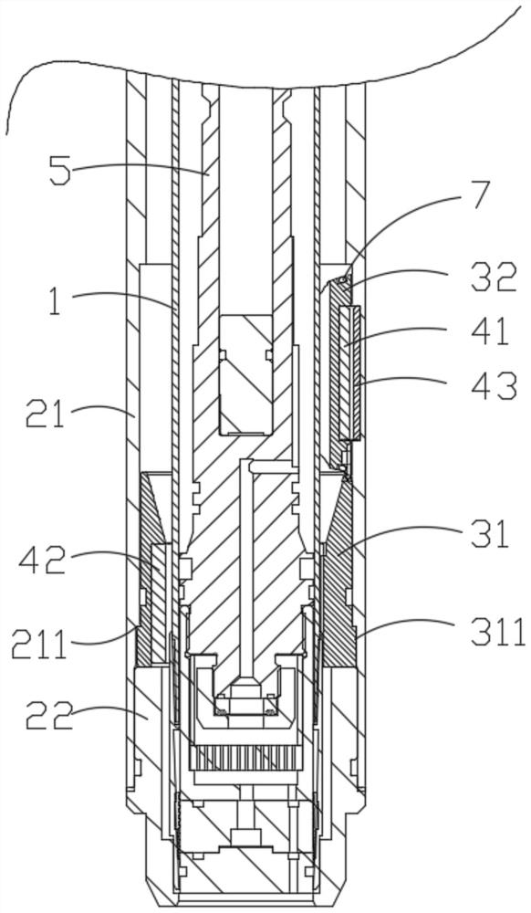
[0038] Such as Figure 1-Figure 5 As shown, the magnetically triggered multi-directional pressure-maintaining coring device disclosed in this embodiment includes a core barrel 1, an outer barrel 2, a flap valve 3, an inner rod 5, a core catcher 6 and a core drilling tool. The core device 6 is arranged inside the lower end of the core barrel 1 .
[0039] The flap valve 3 includes a valve seat 31 and a sealing disc 32. The valve seat 31 is coaxially installed on the inner wall of the outer cylinder 2. A first sealing ring is provided between the outer wall of the valve seat 31 and the inner wall of the outer cylinder 2. The outer circumference of the flap valve 3 The slot is equipped with a second seal ring 7 .
[0040] One end of the sealing disc 32 is movably connected with the upper end of the valve seat 31 . Optionally, the valve seat 31 can be rotatably connected with the sealing disc 32 through a pin shaft.
[0041] A first magnetic piece 41 is installed on the sealing ...
Embodiment 2
[0055] In this embodiment, at least one limiting protrusion 311 is provided on the outer wall of the valve seat 31 . The limiting protrusion 311 is integrally manufactured with the valve seat 31 . The quantity of the limiting protrusions 311 is reasonably set according to needs, and it is preferable to arrange at least two limiting protrusions 311 at equal intervals along the circumferential direction of the valve seat 31 .
[0056] It is worth noting that the top surface of the limiting protrusion 311 is lower than the first sealing ring on the valve seat 31 .
[0057] The outer cylinder 2 includes an upper outer cylinder 21 and a lower outer cylinder 22 . The inner wall of the upper outer cylinder 21 has a limit groove 211 adapted to the limit protrusion 311. Taking the two symmetrically disposed limit protrusions 311 on the outer wall of the valve seat 31 as an example, the inner wall of the upper outer cylinder 21 has two symmetrically disposed Limiting groove 211.
[00...
PUM
 Abstract
Description
Claims
Application Information
 - R&D
- Intellectual Property
- Life Sciences
- Materials
- Tech Scout
- Unparalleled Data Quality
- Higher Quality Content
- 60% Fewer Hallucinations
Browse by: Latest US Patents, China's latest patents, Technical Efficacy Thesaurus, Application Domain, Technology Topic, Popular Technical Reports.
© 2025 PatSnap. All rights reserved.Legal|Privacy policy|Modern Slavery Act Transparency Statement|Sitemap|About US| Contact US: help@patsnap.com


