Pipe hoop-shaped parallel broadband particle damper and design method thereof

A particle shock absorber, parallel technology, applied in the design characteristics of spring/shock absorber, shock absorber, inertia effect shock absorber, etc., can solve maintenance difficulties, high cost of shock absorber, limited use of space, etc. problem, to achieve the effect of flexible application, good vibration reduction effect and low processing cost

Active Publication Date: 2022-01-21
TSINGHUA UNIV
View PDF5 Cites 0 Cited by
  • Summary
  • Abstract
  • Description
  • Claims
  • Application Information

AI Technical Summary

Problems solved by technology

However, the existing vibration damping devices have defects such as high cost, limited use space and difficult maintenance.

Method used


Image

  • Pipe hoop-shaped parallel broadband particle damper and design method thereof
  • Pipe hoop-shaped parallel broadband particle damper and design method thereof
  • Pipe hoop-shaped parallel broadband particle damper and design method thereof

Examples


Embodiment 1

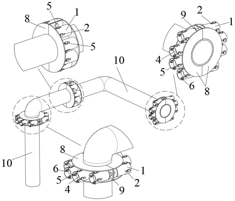
[0057] Please refer to the attached Figure 1-13 , the purpose of this embodiment is to provide a tubular hoop-shaped parallel broadband particle damper, including: a multi-section tubular structure 10, the tubular structure 10 is circular or square, so as to be suitable for various types of cross-sections 10 Vibration reduction of tubular structure. A parallel broadband particle damper is arranged between the multi-section tubular structures 10; the parallel broadband particle damper consists of a tubular hoop-shaped parallel broadband particle damper for axial vibration reduction, and a radial vibration damper for radial vibration reduction. It is composed of a tubular hoop-shaped parallel broadband particle damper.

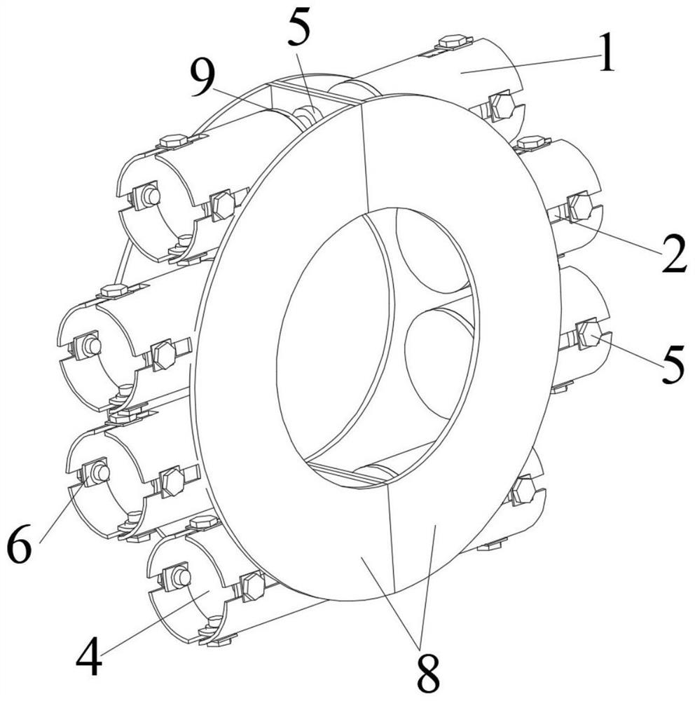
[0058] Among them, the tubular hoop-shaped parallel broadband particle damper for axial vibration reduction is provided with a cylindrical cavity 1 whose axis is parallel to the axis of the tubular structure 10, and a cylindrical cavity whose axis is parallel ...

Embodiment 2

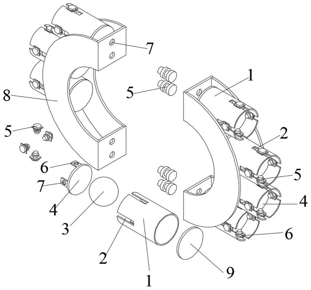
[0064] The purpose of this embodiment is to provide a design method for a tubular hoop-shaped parallel broadband particle damper, including the following steps: determining the total mass and number of particles 3 in the tubular hoop-shaped parallel broadband particle damper , radius and movement distance; according to the design information of the particle 3, the size of the two cylindrical cavities 1 and the size of the elongated hole 2 are determined.

[0065] Specifically, the vibration characteristics of the tubular structure 10 include mass m, damping coefficient c and stiffness k, and the displacement, velocity and acceleration of the tubular structure 10 are x, and The mass m is the sum of the mass of the tubular structure 10 and other components in the particle damper except the particle 3, and the mass of the particle 3 is m p , the displacement, velocity and acceleration of particle 3 are x p , and d is the movement distance of the particles 3, g is the acce...


PUM


Abstract

The invention belongs to the technical field of energy dissipation and vibration reduction of pipe structures, and particularly relates to a pipe hoop-shaped parallel broadband particle damper and a design method thereof. The pipe hoop-shaped parallel broadband particle damper comprises multiple sections of pipe structures, wherein parallel broadband particle dampers are arranged among the multiple sections of pipe structures; a cylindrical cavity with the axis parallel to the axis of a pipe structure is formed in the pipe hoop-shaped parallel broadband particle damper used for axial damping, and particles are arranged in the cylindrical cavity with the axis parallel to the axis of the pipe structure; and a cylindrical cavity with the axis perpendicular to the axis of the pipe structure is formed in the pipe hoop-shaped parallel broadband particle damper for radial damping, and particles are arranged in the cylindrical cavity with the axis perpendicular to the axis of the pipe structure. The pipe hoop-shaped parallel broadband particle damper and the design method thereof have the beneficial effects that when the pipe structure vibrates, effective control over vibration of the pipe structure is achieved through momentum exchange and collision energy consumption when particles collide with the pipe structure, normal use of the pipe structure is recovered, and adaptability, durability and safety of the pipe structure are improved.

Description

technical field [0001] The invention belongs to the technical field of energy dissipation and vibration reduction of tubular structures, and in particular relates to a tubular hoop-shaped parallel broadband particle damper and a design method thereof. Background technique [0002] Pipe structures are widely used in daily life and production. For example, pipes in pipe structures are used as a mode of transportation. Compared with traditional transportation methods such as roads, railways, and waterways, the transportation is highly efficient, flexible, and economically cost-effective. It is the most important gas and fluid transportation method, and is widely used in important links such as industry, agriculture, petrochemical production and transportation. However, due to the unreasonable design of the pipe structure, the unbalanced mechanical vibration and the internal gas / liquid pulse effect, the pipe structure is extremely prone to vibration, which will affect the normal...

Claims


Application Information

Patent Timeline
IPC IPC(8): F16L55/02F16F7/10F16F7/108F16F15/02F16F15/023F16F15/08G06F17/10
CPCF16L55/02F16F7/10F16F7/108F16F15/02F16F15/023F16F15/08G06F17/10F16F2230/0005F16F2228/04
Inventor 潘鹏王宝顺王海深
Owner TSINGHUA UNIV
Why Eureka
Try Eureka