A gravity penetrating device and method of a seabed sediment pore pressure observation probe rod
A seabed sediment and pore pressure technology, applied in measuring devices, measuring fluid pressure, soil material testing, etc., can solve problems such as polluting the marine ecological environment, disturbing seabed sediments, and affecting observation results, achieving high safety in field work , Reduce equipment deployment costs, and facilitate integration and deployment
- Summary
- Abstract
- Description
- Claims
- Application Information
AI Technical Summary
Problems solved by technology
Method used
Image
Examples
Embodiment 1
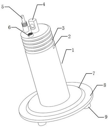
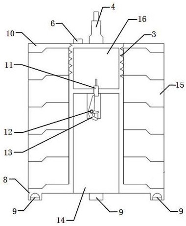
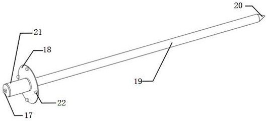
[0076] A gravity penetration device of a probe rod for observation of pore pressure of seabed sediments, comprising a control cabin 1 and an observation rod,
[0077] In the control cabin 1, a sealed pressure chamber 16 and an open assembly chamber 14 for connecting the observation probe are formed through the baffle. An underwater acoustic transducer 6, a pressure sensor 5 and an attitude sensor are respectively installed on the ring 4 in the circumferential direction, and a mechanical lock 13 is installed on the baffle plate in the assembly cabin 14, which is driven by the first drive mechanism to rotate and realize opening and closing. A first acquisition control system and a first battery pack for power supply are installed in the cabin 16, and the first acquisition control system is respectively electrically connected with the underwater acoustic transducer 6, the pressure sensor 5, the attitude sensor and the first drive mechanism. In the invention, the first driving mec...
Embodiment 2
[0094] A method for using a gravity penetration device of a probe rod for observing pore pressure of seabed sediments, comprising the following steps:
[0095] A. Assembly:
[0096] A1. The whole observation probe rod is hoisted through the hanger 32, the probe rod body 19 is placed on the support plate 28, and the observation probe rod stop plate 18 is close to the probe rod limit plate 26;
[0097] A2. Place the control cabin 1 with the counterweight 15 installed in the support frame 25 on the sliding seat 24;
[0098] A3. Plug and install the data acquisition cabin 21 of the observation probe rod and the assembly cabin 14 at one end of the control cabin 1, and drive the mechanical lock 13 to lock through the electric push rod 11, so that the mechanical lock 13 and the second lifting ring of the data collection cabin 21 are locked. 17 Connect, connect the hook of the cable 33 with the first lifting ring 4 on the control cabin 1;
[0099] B. Deploy:
[0100] B1. Keep the a...
PUM
 Abstract
Description
Claims
Application Information
 - R&D
- Intellectual Property
- Life Sciences
- Materials
- Tech Scout
- Unparalleled Data Quality
- Higher Quality Content
- 60% Fewer Hallucinations
Browse by: Latest US Patents, China's latest patents, Technical Efficacy Thesaurus, Application Domain, Technology Topic, Popular Technical Reports.
© 2025 PatSnap. All rights reserved.Legal|Privacy policy|Modern Slavery Act Transparency Statement|Sitemap|About US| Contact US: help@patsnap.com


