
Heat preservation and insulation aluminum profile and preparation method thereof

A technology for thermal insulation and aluminum profiles, applied in the field of aluminum profiles, can solve the problems of long time spent tightening screws, affecting assembly efficiency, etc., and achieve the effect of improving assembly efficiency and saving time.

Active Publication Date: 2022-01-25
东阳市江南铝材有限公司
View PDF5 Cites 0 Cited by
  • Summary
  • Abstract
  • Description
  • Claims
  • Application Information

AI Technical Summary

Problems solved by technology

[0002] In the process of building decoration, aluminum profiles are often used to separate some buildings with large spaces. Because the aluminum profiles have good thermal insulation properties after separation, they are widely used by people. The aluminum profiles in the prior art The profile needs to use a lot of screws to fix its connection points during the assembly process. Due to the large number of screws used, it takes a long time to tighten the screws during the assembly process, which seriously affects its assembly efficiency.

Method used


Image

  • Heat preservation and insulation aluminum profile and preparation method thereof
  • Heat preservation and insulation aluminum profile and preparation method thereof
  • Heat preservation and insulation aluminum profile and preparation method thereof

Examples


Embodiment 1

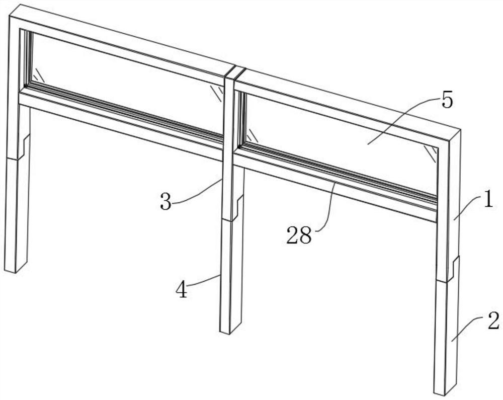
[0032] Such as Figure 1-7As shown, this embodiment proposes a thermal insulation aluminum profile, including a main aluminum frame 1, the lower end surface of the main aluminum frame 1 is fitted with a No. 1 extension frame 2, and the end of the main aluminum frame 1 is fitted and installed There is a connecting aluminum frame 3, and the lower end surface of the connecting aluminum frame 3 is fitted with a No. 2 extension frame 4, between the main aluminum frame 1 and the No. 1 extension frame 2 and between the connecting aluminum frame 3 and the No. 2 extension frame 4 There are clamping parts installed between them, and an aluminum beam 28 is installed between the connecting aluminum frame 3 and the main aluminum frame 1. The aluminum beam 28 plays the role of supporting the installation frame 16. The aluminum beam 28 and the connecting aluminum frame 3 and the main aluminum frame 1 are provided with fixing parts, the side and top surface of the main aluminum frame 1, the s...

Embodiment 2

[0034] The scheme in embodiment 1 is further introduced below in combination with specific working methods, see the following description for details:

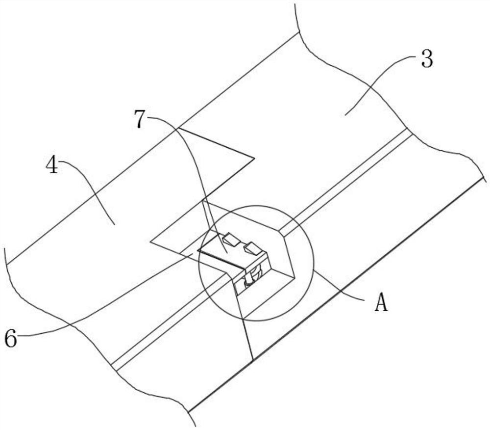
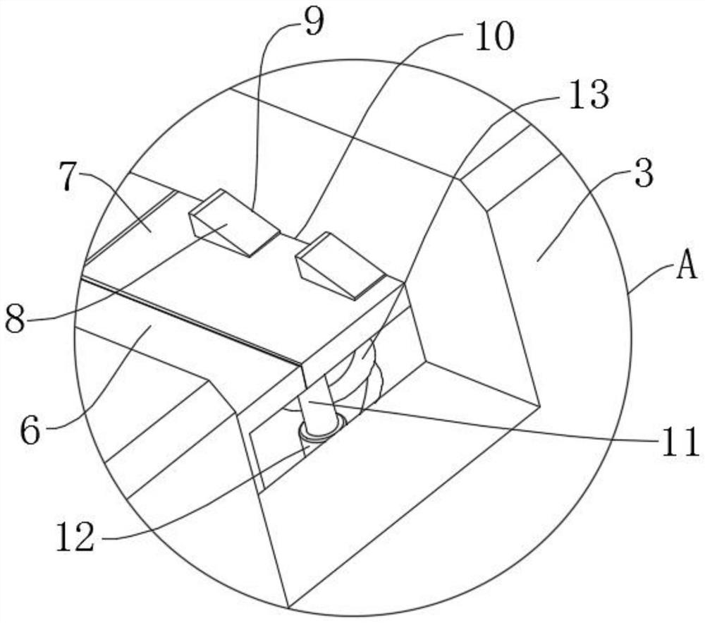
[0035] As a preferred embodiment, on the basis of the above method, further, the clamping part includes a positioning frame 6 extending on the front end of the second extension frame 4 and the front end of the first extension frame 2, and the positioning frame 6 plays a positioning role. Positioning slot 10 is provided at the lower edge of the rear end face of the main aluminum frame 1 and the lower edge of the rear end face of the connecting aluminum frame 3, and the positioning frame 6 fits inside the positioning slot 10, and the positioning slot 10 plays the role of The function of restricting the positioning frame 6 is that the side of the positioning frame 6 fits through and elastically installs a fixing seat 7, and the side of the fixing seat 7 extends with a triangular bump 8, and the triangular bump 8 fits through the i...

Embodiment 3

[0046] The schemes in Embodiment 1 and Embodiment 2 are further introduced below in conjunction with specific working methods, see the following description for details:

[0047] Specifically, when in use, the installation frame 16 is placed in the frame groove 17 on the main aluminum frame 1, and then the clamping column 15 on the connecting aluminum frame 3 is docked with the clamping groove 14 on the main aluminum frame 1 At this time, the installation frame 16 is located in the frame groove 17 on the connecting aluminum frame 3, then the bracket 27 is pressed down, and the aluminum beam 28 is placed between the main aluminum frame 1 and the connecting aluminum frame 3, this When the installation frame 16 is located in the frame groove 17 on the aluminum beam 28, then the bracket 27 is released, so that the bracket 27 resets into the bracket groove 38 on the aluminum beam 28 under the action of the jacking spring 35, and at the same time The limit block 37 on the seat 27 en...


PUM


Abstract

The invention relates to the field of aluminum profiles, in particular to a heat preservation and insulation aluminum profile. The heat preservation and insulation aluminum profile comprises a main aluminum profile frame, wherein a first extension frame is installed on the lower end face of the main aluminum profile frame in an attached mode, a connecting aluminum profile frame is installed at the end of the main aluminum profile frame in an attached mode, and a second extension frame is installed on the lower end face of the connecting aluminum profile frame in an attached mode; clamping pieces are installed between the main aluminum profile frame and the first extension frame and between the connecting aluminum profile frame and the second extension frame correspondingly, an aluminum profile cross beam is installed between the connecting aluminum profile frame and the main aluminum profile frame in an attached mode, and fixing and supporting pieces are arranged between the aluminum profile cross beam and the connecting aluminum profile frame and between the aluminum profile cross beam and the main aluminum profile frame; frame grooves are formed in the side face and the top face of the main aluminum profile frame, the side face of the connecting aluminum profile frame and the upper end face of the aluminum profile cross beam correspondingly. According to the heat preservation and insulation aluminum profile, the assembling efficiency is effectively improved, it is guaranteed that a bracket does not slide down, glass can be conveniently disassembled and assembled, and the using convenience can be guaranteed while carrying is convenient.

Description

technical field [0001] The invention relates to the field of aluminum profiles, in particular to a thermal insulation aluminum profile and a preparation method thereof. Background technique [0002] In the process of building decoration, aluminum profiles are often used to separate some buildings with large spaces. Because the aluminum profiles have good thermal insulation properties after separation, they are widely used by people. The aluminum profiles in the prior art During the assembly process of the profile, a large number of screws are needed to fix its connection points. Due to the large number of screws used, it takes a long time to tighten the screws during the assembly process, which seriously affects its assembly efficiency. Contents of the invention [0003] (1) The technical problem to be solved by the present invention is: the time spent for tightening the screw in the assembly process is longer, seriously affecting the problem of its assembly efficiency. ...

Claims


Application Information

Patent Timeline
IPC IPC(8): E04B2/76E04B2/82E04B1/78
CPCE04B2/76E04B2/766E04B2/7409E04B1/78
Inventor 林东鹏
Owner 东阳市江南铝材有限公司
Learn More