Sector-shaped slope crack monitoring device and monitoring method thereof

A monitoring device and sector technology, applied in the field of geotechnical engineering monitoring and geological disasters, can solve the problems of large time domain for simple manual monitoring, weakened pertinence of monitoring technical methods, and different quality levels of observation data, and achieve installation and deployment. Strong field adaptability, reduced high requirements, and reliable monitoring results

Pending Publication Date: 2022-01-25
重庆益尔感知数据研究院有限公司 +1
View PDF0 Cites 0 Cited by
  • Summary
  • Abstract
  • Description
  • Claims
  • Application Information

AI Technical Summary

Problems solved by technology

[0007] Manual simple monitoring has a large and uncertain gap in the monitoring time domain, and the quality of observation data varies, making it difficult to meet the requirements of long-term continuous observation
[0008] In the existing automatic monitoring technology, different displacement sensing methods are based on the identified surface cracks, and the monitoring work is carried out for the change of its width. It is often difficult to identify cracks. At this time, the pertinence of the monitoring technology is greatly weakened, and there is even the possibility of misjudgment.
In addition, for slopes with potential deformation that have not yet developed ground fissures, the aforementioned conventional monitoring methods are highly dependent on field identification and evaluation, and the deployment of monitoring equipment is highly demanding

Method used


Image

  • Sector-shaped slope crack monitoring device and monitoring method thereof
  • Sector-shaped slope crack monitoring device and monitoring method thereof
  • Sector-shaped slope crack monitoring device and monitoring method thereof

Examples


Embodiment Construction

[0050] In order to describe the technical content, structural features, achieved goals and effects of the present invention in detail, the following will be described in detail in conjunction with the embodiments and accompanying drawings.

[0051] The technical solutions of the present invention will be clearly and completely described below in conjunction with the accompanying drawings. Apparently, the described embodiments are some of the embodiments of the present invention, but not all of them. Based on the embodiments of the present invention, all other embodiments obtained by persons of ordinary skill in the art without making creative efforts belong to the protection scope of the present invention. In the description of the present invention, it should be noted that the terms "center", "upper", "lower", "left", "right", "vertical", "horizontal", "inner", "outer" etc. The indicated orientation or positional relationship is based on the orientation or positional relation...


PUM


Abstract

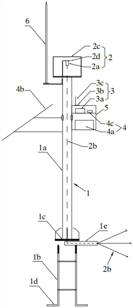
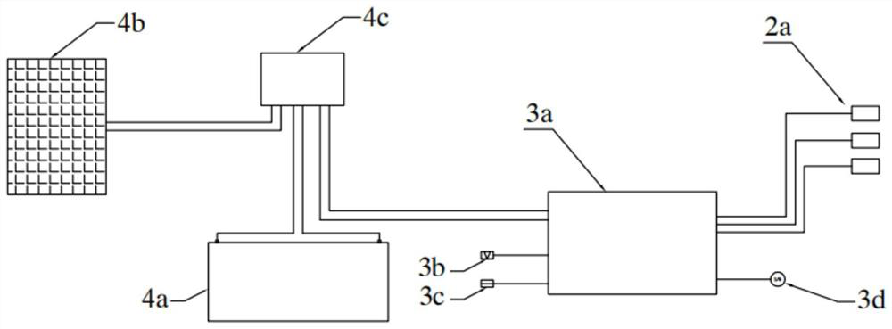
The invention discloses a sector-shaped slope crack monitoring device and a monitoring method thereof. The sector-shaped slope crack monitoring device comprises an installation stand column, a displacement sensor bundling assembly, a data acquisition and transmission assembly and a power supply assembly, the displacement sensor bundling assembly comprises a plurality of displacement sensors and steel strands connected with the displacement sensors, and the displacement sensors are installed at the top of the installation stand column; the steel strand penetrates through the installation stand column and is arranged underground in a sector shape, the data collection and transmission assembly is connected with the displacement sensor bundling assembly and the power supply assembly, data collection, preprocessing and remote transmission are achieved, power is supplied through the power supply assembly, and the data collection and transmission assembly and the power supply assembly are both arranged on the installation stand column. The steel strands connected with the sensors are arranged in a sector shape to form a plurality of monitoring lines, so that the monitoring coverage and capture range is expanded, the monitoring coverage wide area is improved, the monitoring capture blind area is overcome, the crack width and development trend can be rapidly and accurately represented, and the reliability, practicability and comprehensiveness of a monitoring result are improved.

Description

technical field [0001] The invention relates to the technical field of geological disaster and geotechnical engineering monitoring, in particular to a fan-shaped slope crack monitoring device and a monitoring method thereof. Background technique [0002] Ground fissures are geological phenomena in which surface rocks and soils are cracked under the action of natural or human factors, and cracks of a certain length and width are formed. Ground fissures are a slowly developing progressive disaster geology. Affected by the geological environment and human factors, the development of ground fissures is gradual and periodic. As time changes, the hazards of ground fissures make the surrounding area Deformation and stress fields are generated within the geological body. For slope disasters, the development of surface fissures is the most common deformation characterization, and its development trend has a strong correlation with the overall stability of the slope. Therefore, monit...

Claims


Application Information

Patent Timeline
Patent Type & Authority Applications(China)
IPC IPC(8): G01B21/02
CPCG01B21/02
Inventor 魏世玉李华梅李川马希见江杨倩吴传伟
Owner 重庆益尔感知数据研究院有限公司
Why Eureka
Try Eureka