Combined micro-pump control device

A technology of a control device and a micro-pump, which is applied in the directions of hypodermic injection devices, devices introduced into the body, and devices for drugs, etc., can solve the problem that the drugs that cannot be mixed well, have no flushing function, and cannot be injected can be maintained at the required level. temperature and other issues, to achieve the effect of solving the more stringent requirements of storage environment temperature and ensuring the efficacy of drugs

Active Publication Date: 2022-01-28
SHANDONG UNIV QILU HOSPITAL
View PDF4 Cites 0 Cited by
  • Summary
  • Abstract
  • Description
  • Claims
  • Application Information

AI Technical Summary

Problems solved by technology

[0002] During the treatment of many patients, micro-injection is required, and the minimum rate of micro-injection can reach 0.1mL / h. long, there may be untimely dispensing of medicines, affecting the treatment of patients
The reason why the medicine needs to be dispensed every time the medicine is injected is also because some medicines need to be stored in a constant temperature range (such as a certain temperature between 4 and 20°C) to ensure that the medicine has the efficacy of the medicine. It also determines that multiple drugs cannot be prepared at one time and placed on the existing micro-injection device, because the existing micro-injection device does not have a temperature control device and cannot maintain the drug to be injected at the required temperature
[0003] Furthermore, some drugs that are injected before and after the patient cannot be mixed in the injection line, which requires flushing the injection line (commonly known as flushing) after the first drug is injected, and flushing The liquid used in the tube also has different requirements, some require flushing with saline, and some require flushing with sugar water, which also determines that multiple drugs cannot be equipped at one time, because the existing micro-injection device does not have the function of flushing the tube

Method used


Image

  • Combined micro-pump control device
  • Combined micro-pump control device
  • Combined micro-pump control device

Examples


Embodiment Construction

[0019] The present invention will be further described below in conjunction with the accompanying drawings and embodiments.

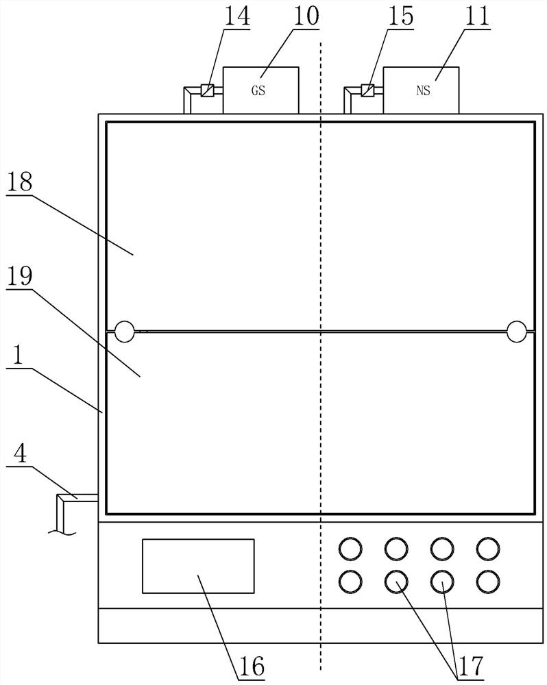
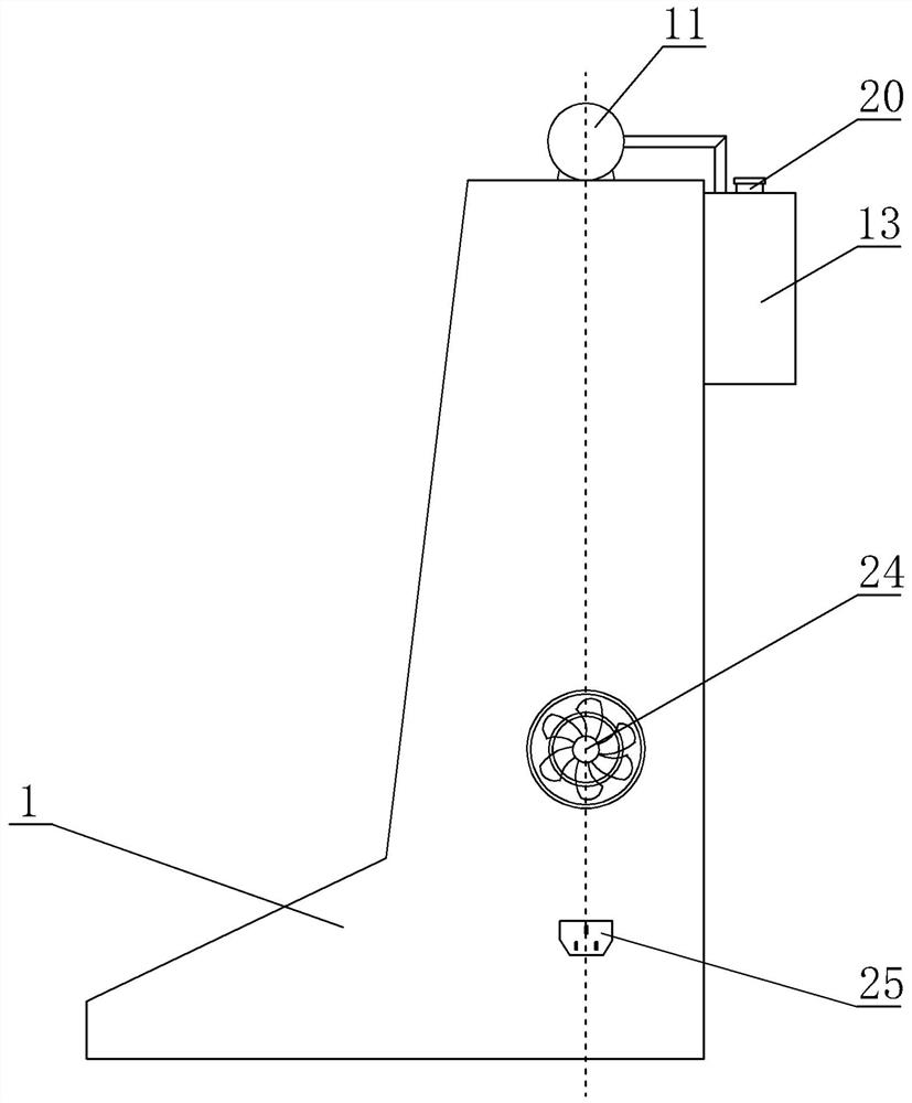
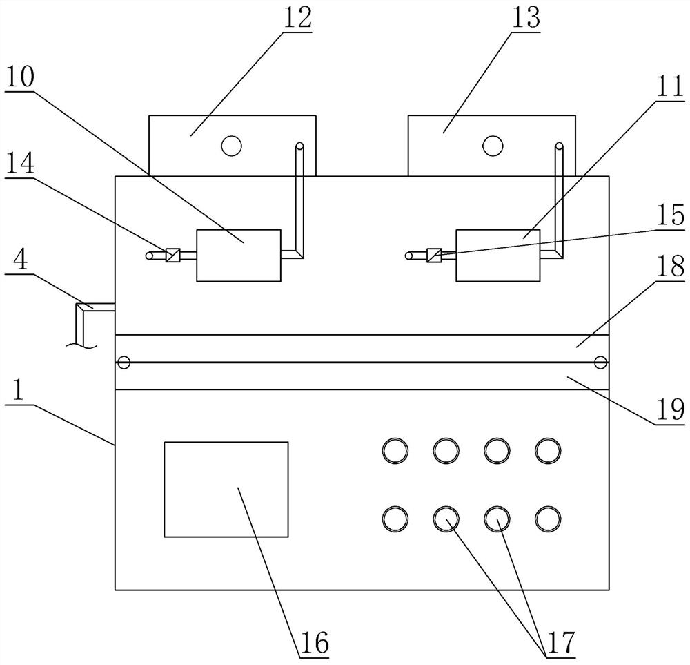
[0020] Such as figure 1 , figure 2 with image 3 As shown, the front view, right view and top view of the combined micropump control device of the present invention are respectively given, Figure 4 The front view of the upper cover and the lower cover of the combined micropump control device of the present invention using the perspective drawing method is given, Figure 5 The front view of the upper cover and the lower cover of the combined micropump control device of the present invention using the perspective drawing method is given, Image 6 The circuit principle diagram of the circuit part in the present invention is given, the combined micropump control device shown is composed of a housing 1, an injection main pipe 4, a plurality of microinjection devices, a saline flushing pump 10, a sugar water flushing pump 11, and a saline container 12 ,...


PUM


Abstract

A combined micro-pump control device comprises a shell, an injection main tube, a plurality of micro-injection devices, a saline flushing pump, a sweet water flushing pump and a circuit part, a micro-pump bin and a circuit bin are arranged in the shell, and each micro-injection device is composed of a micro-pump-in device, an injector, an injection branch tube and an injection electric control valve. The injectors are clamped on the micro pump-in devices, one ends of the injection branch tubes are communicated with the injection main tube, the other ends of the injection branch tubes are communicated with the liquid outlet of the injector, and liquid outlets of the saline water flushing pump and the sweet water flushing pump are communicated with the injection main tube through pipelines. According to the combined micro-pump control device, multiple times of micro injection of a patient can be completed by simultaneously preparing multiple (such as four) medicines at a time, the injection main tube can be flushed, the injection speed, pipeline flushing and the injection frequency and injection time of each medicine can be braked and controlled, and the defect that an existing micro-injection device cannot be provided with multiple kinds of medicine at the same time is overcome.

Description

technical field [0001] The present invention relates to a micropump control device, more specifically, to a combined micropump control device. Background technique [0002] During the treatment of many patients, micro-injection is required, and the minimum rate of micro-injection can reach 0.1mL / h. For a long time, there may be untimely dispensing of medicines, which will affect the treatment of the patient's condition. The reason why the medicine needs to be dispensed every time the medicine is injected is also because some medicines need to be stored in a constant temperature range (such as a certain temperature between 4 and 20°C) to ensure that the medicine has the efficacy of the medicine. It is also determined that multiple medicines cannot be prepared at one time and placed on the existing microinjection device, because the existing microinjection device does not have a temperature control device and cannot maintain the medicine to be injected at the required tempera...

Claims


Application Information

Patent Timeline
Patent Type & Authority Applications(China)
IPC IPC(8): A61M5/142A61M5/00
CPCA61M5/142A61M5/001A61M2205/36A61M2205/3606A61M2205/3653A61M2205/3368
Inventor 王昊韩辉
Owner SHANDONG UNIV QILU HOSPITAL
Why Eureka
Try Eureka