Slow-dripping device for preparing antiviral drug HIV intermediate

An antiviral drug and system technology, applied in the direction of feeding device, chemical/physical process, chemical instrument and method, etc., can solve the error, cannot grasp the dripping rate well, and cannot adjust the dripping rate, etc. problem, to achieve the effect of stable movement, improved accuracy, safe and effective dripping operation

Inactive Publication Date: 2022-01-28
HENAN UNIV OF CHINESE MEDICINE
View PDF0 Cites 0 Cited by
  • Summary
  • Abstract
  • Description
  • Claims
  • Application Information

AI Technical Summary

Problems solved by technology

[0003] The object of the present invention is to provide a kind of antiviral drug HIV intermediate standby slow dripping device, to solve the traditional dripping equipment proposed in the above-mentioned background technology, the rate of dripping cannot be well grasped by manual dripping, and then cannot be achieved. The adjustment of the drip rate, so when preparing the drug mixture, it causes a large error problem

Method used


Image

  • Slow-dripping device for preparing antiviral drug HIV intermediate
  • Slow-dripping device for preparing antiviral drug HIV intermediate
  • Slow-dripping device for preparing antiviral drug HIV intermediate

Examples


Embodiment 1

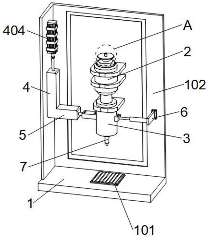
[0033] refer to Figure 1-6 A standby slow-dropping device for an antiviral drug HIV intermediate as shown, including a workbench 1, a placement plate 101 is fixedly installed at the center of the upper surface of the workbench 1, and a L plate is vertically fixed on the left side and rear side of the upper surface of the workbench 1. Shaped splash guard 102, the upper surface of the L-shaped splash guard 102 is fixed with a liquid storage bottle 2 through a mounting bracket, and a slow drip assembly is arranged below the liquid storage bottle 2, and the surface of the L-shaped splash guard 102 is located The buffer assembly is arranged on the right side of the slow drop assembly, and a propulsion assembly is arranged above the short side surface of the L-shaped splash guard 102. The components are structurally matched with the buffer component, and the lower end of the slow drip component is provided with a dropper 7 .

[0034]Based on the above structure, when the device is...

Embodiment 2

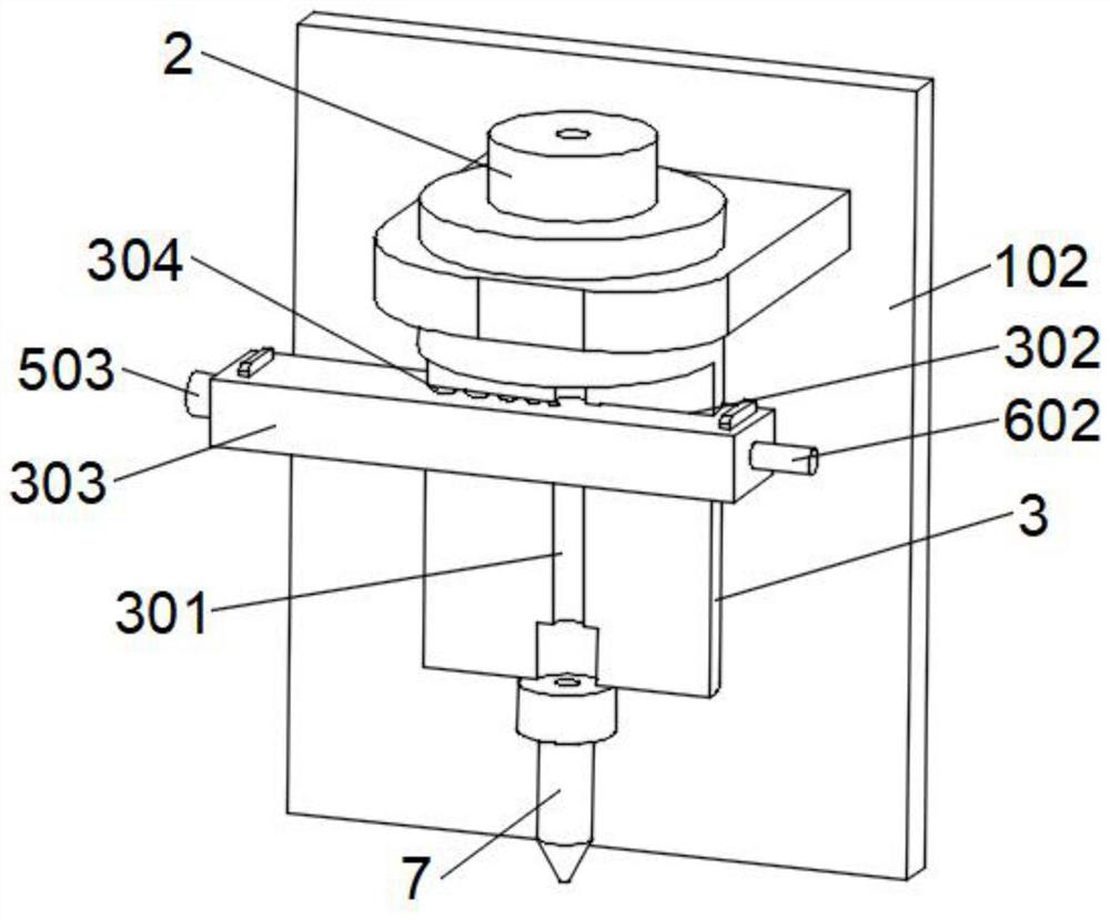
[0036] combine figure 1 , image 3 and Figure 5 As shown, based on the above-mentioned embodiment 1, the slow drip assembly includes a slow drip column body 3 fixedly installed on the surface of the L-shaped splash guard 102 through a mounting bracket, and the upper end of the slow drip column body 3 is fixed to the lower end of the liquid storage bottle 2 connection, the inside of the slow drip column body 3 is opened with a diversion hole 301, and its diversion hole 301 communicates with the inside of the liquid storage bottle 2, and the interior of the slow drop column body 3 is provided with a penetrating limit chute 302, the limit chute 302 A slow-drip plate 303 is slidably installed inside, and slow-drip holes 304 with different diameters are provided at equal intervals on the surface of the slow-drip plate 303 near the middle. The tube 7 is fixed at the lower end of the slow drip column body 3, and the drop tube 7 communicates with the diversion hole 301, and the gui...

Embodiment 3

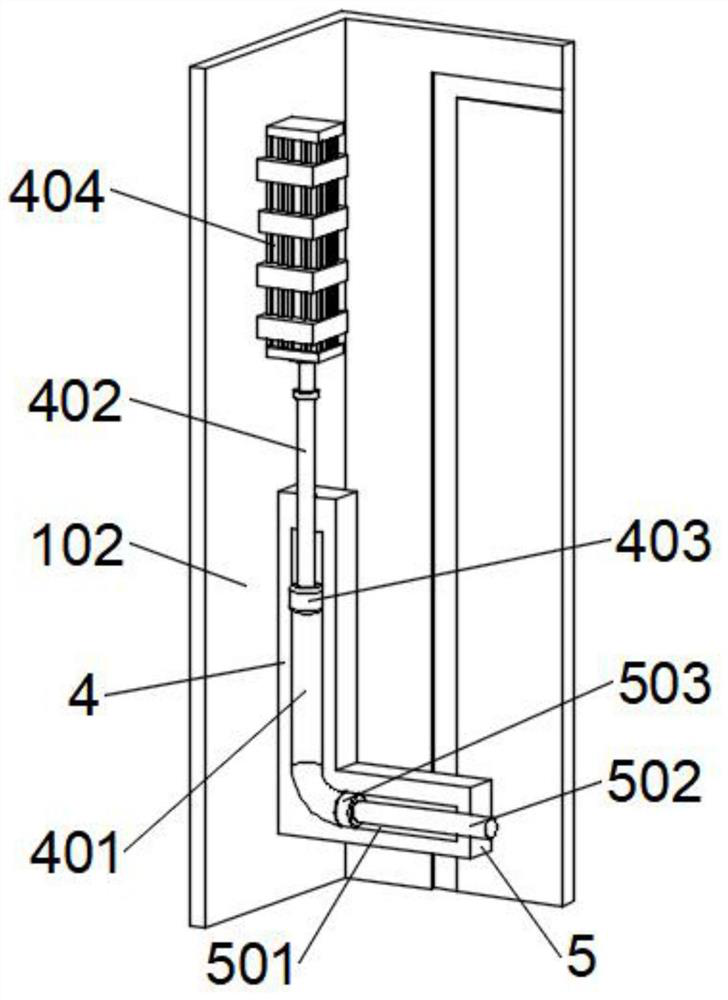
[0038] combine figure 1 and figure 2 As shown, based on the above-mentioned embodiment 1 or 2, the propulsion assembly includes a vertical plate 4 fixedly installed on the surface of the L-shaped splash guard 102, the upper end of the vertical plate 4 is provided with a pressure guide hole A401, and the port of the pressure guide hole A401 is slidingly inserted There is a guide rod A402, the end of the guide rod A402 located in the pressure guide hole A401 is fixed with a piston A403, and the outer surface of the piston A403 is slidingly connected with the inner wall surface of the pressure guide hole A401, and the surface of the L-shaped splash guard 102 is located on the vertical plate 4 A small hydraulic cylinder 404 is fixed on the upper part through a fixed frame, and the telescopic end of the small hydraulic cylinder 404 is fixedly connected with the upper end of the guide rod A402. When the small hydraulic cylinder 404 works, the telescopic end of the small hydraulic c...


PUM


Abstract

The invention relates to the technical field of medicine preparation auxiliary devices, in particular to a slow-dripping device for preparing an antiviral drug HIV intermediate. The device comprises a workbench, wherein a placement plate is fixedly mounted at the center of the upper surface of the workbench, L-shaped splash-proof guard plates are vertically fixed to the left side and the rear side of the upper surface of the workbench, a liquid storage bottle is fixedly mounted above the surface of the long edge of the L-shaped splash-proof guard plate through a mounting frame, a slow dripping assembly is arranged below the liquid storage bottle, and a buffer assembly is arranged on the surface of the L-shaped splash-proof guard plate and located on the right side of the slow dripping assembly. According to the invention, the sliding lead of the slow dripping plate is changed along with the change of the expansion and contraction amount of the telescopic end of a small hydraulic cylinder, then the slow dripping holes with different sizes are aligned with the flow guide holes, the dripping speed of liquid medicine can be effectively adjusted, the slow dripping speed of the device is adjusted, the slow dripping speed is controlled, the use requirements under different conditions are met, and the dispensing accuracy is further improved.

Description

technical field [0001] The invention relates to the technical field of auxiliary devices for preparation of medicines, in particular to a slow-drip device for preparing HIV intermediates of antiviral drugs. Background technique [0002] The disease caused by HIV infection is called AIDS, and its full name is Acquired Immunodeficiency Syndrome. The patient's immune function is partially or completely lost, and the number of CD4+ cells is reduced, followed by opportunistic infection or tumor. The clinical manifestations are various. Diverse, when preparing antiviral drug HIV intermediates, when using a dropper for dripping, traditional dripping equipment cannot grasp the rate of dripping well through manual dripping, and thus cannot adjust the rate of dripping , so when preparing the drug mixture, it causes a large error. In view of this, we propose a standby slow drop device for antiviral drug HIV intermediates. Contents of the invention [0003] The object of the present ...

Claims


Application Information

Patent Timeline
Patent Type & Authority Applications(China)
IPC IPC(8): B01J4/00
CPCB01J4/007B01J4/008B01J2204/002
Inventor 冯龙路武豪高剑峰王白燕徐华明冯书营李志慧郑文锦耿宇轩李青
Owner HENAN UNIV OF CHINESE MEDICINE
Why Eureka
Try Eureka