Synchronizing device of aerated concrete block side face cutting machine

A technology of aerated concrete and synchronization device, which is applied in the direction of stone processing tools, stone processing equipment, work accessories, etc., and can solve the problem of not having a synchronization device for plate knives of side cutters, which cannot meet the requirements of existing products, construction technology, cutting It is difficult to guarantee the dimensional accuracy of the green body and other problems, so as to achieve the effects of easy maintenance and repair, improved timeliness and low cost

Pending Publication Date: 2022-01-28
DONGYUE MACHINERY GRP
View PDF0 Cites 2 Cited by
  • Summary
  • Abstract
  • Description
  • Claims
  • Application Information

AI Technical Summary

Problems solved by technology

[0002] The existing aerated concrete block equipment basically does not have a synchronization device that restricts the simultaneous movement of both sides of the side cutter plate knife, resulting in insufficient precision of the existing equipment and related products, unable to meet the existing product requirements and construction technology
Most of the existing aerated concrete block cutting equipment does not have a synchronization device when cutting plates on the side. When the plate knives on both sides are cutting the running green body, it is inevitable that the running of the plate knives on both sides will not be synchronized, which will easily cause unnecessary damage to the green body. , It is also easy to cause the dimensional accuracy of the cut body to be difficult to guarantee, causing certain troubles for the later molding process and product process, time-consuming and laborious, so that it cannot meet the requirements of improving product quality and controlling costs

Method used


Image

  • Synchronizing device of aerated concrete block side face cutting machine
  • Synchronizing device of aerated concrete block side face cutting machine
  • Synchronizing device of aerated concrete block side face cutting machine

Examples


Embodiment Construction

[0014] The following will clearly and completely describe the technical solutions in the embodiments of the present invention with reference to the accompanying drawings in the embodiments of the present invention. Obviously, the described embodiments are only some, not all, embodiments of the present invention.

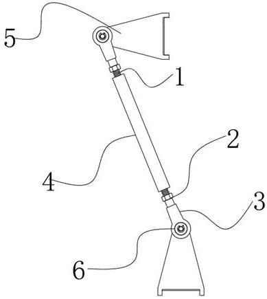
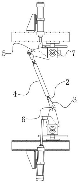
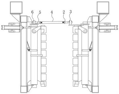
[0015] refer to Figure 1-3 , a synchronous device for aerated concrete block side cutting machine, comprising a hollow connecting rod 4, the inner side of the hollow connecting rod 4 is provided with an internal thread, and both ends of the hollow connecting rod 4 are threadedly connected with a threaded rod 1, two threaded rods 1. A joint bearing 3 is provided at the end far away from the hollow connecting rod 4, and pin rods are inserted in the bearing holes of the two joint bearings 3, and both pin rods are connected with a seat plate 5.

[0016] In the present invention, the two pin rods are provided with annular clamping grooves, and the spacers 6 are clamped i...


PUM


Abstract

The invention relates to a synchronizing device of an aerated concrete block side face cutting machine, which comprises a hollow connecting rod, internal threads are arranged on the inner side of the hollow connecting rod, threaded rods are in threaded connection with the two ends of the hollow connecting rod correspondingly, and joint bearings are arranged at the ends, away from the hollow connecting rod, of the two threaded rods correspondingly; pin rods are inserted into bearing holes of the two knuckle bearings, and the two pin rods are connected with seat plates. Through the parts such as the joint bearing and the connecting rod, machining is easy, the cost is relatively low, equipment operation is stable and reliable, and dismounting and mounting are convenient, so that future maintenance and repair are facilitated, the after-sale cost is effectively reduced, synchronous rotation of a plate cutting tool rest can be achieved, the better cutting effect is achieved, the blank size precision is guaranteed, unnecessary damage to the green body is not prone to being caused, follow-up forming machining of the blank is facilitated, machining manpower is saved on the whole, and timeliness is improved.

Description

technical field [0001] The invention relates to the technical field of aerated concrete block processing, in particular to a synchronous device for a side cutter of an aerated concrete block. Background technique [0002] The existing aerated concrete block equipment basically does not have a synchronization device that restricts the simultaneous movement of both sides of the side cutter plate knife, resulting in insufficient precision of the existing equipment and related products, unable to meet the existing product requirements and construction technology. Most of the existing aerated concrete block cutting equipment does not have a synchronization device when cutting plates on the side. When the plate knives on both sides are cutting the running green body, it is inevitable that the running of the plate knives on both sides will not be synchronized, which will easily cause unnecessary damage to the green body. , It is also easy to cause the dimensional accuracy of the cu...

Claims


Application Information

Patent Timeline
Patent Type & Authority Applications(China)
IPC IPC(8): B28D1/22B28D7/00
CPCB28D1/22B28D7/00
Inventor 孙京伟郭士鹏丁坤
Owner DONGYUE MACHINERY GRP
Why Eureka
Try Eureka