Automatic intelligent cable pay-off machine with temporary processing function
A pay-off machine and functional technology, applied in the field of automated intelligent cable pay-off machines, can solve problems such as long operation time, occupation of human resources, and limited efficiency of pay-off and embedding, so as to reduce labor intensity, human resources and time Effect
- Summary
- Abstract
- Description
- Claims
- Application Information
AI Technical Summary
Problems solved by technology
Method used
Image
Examples
Embodiment 1
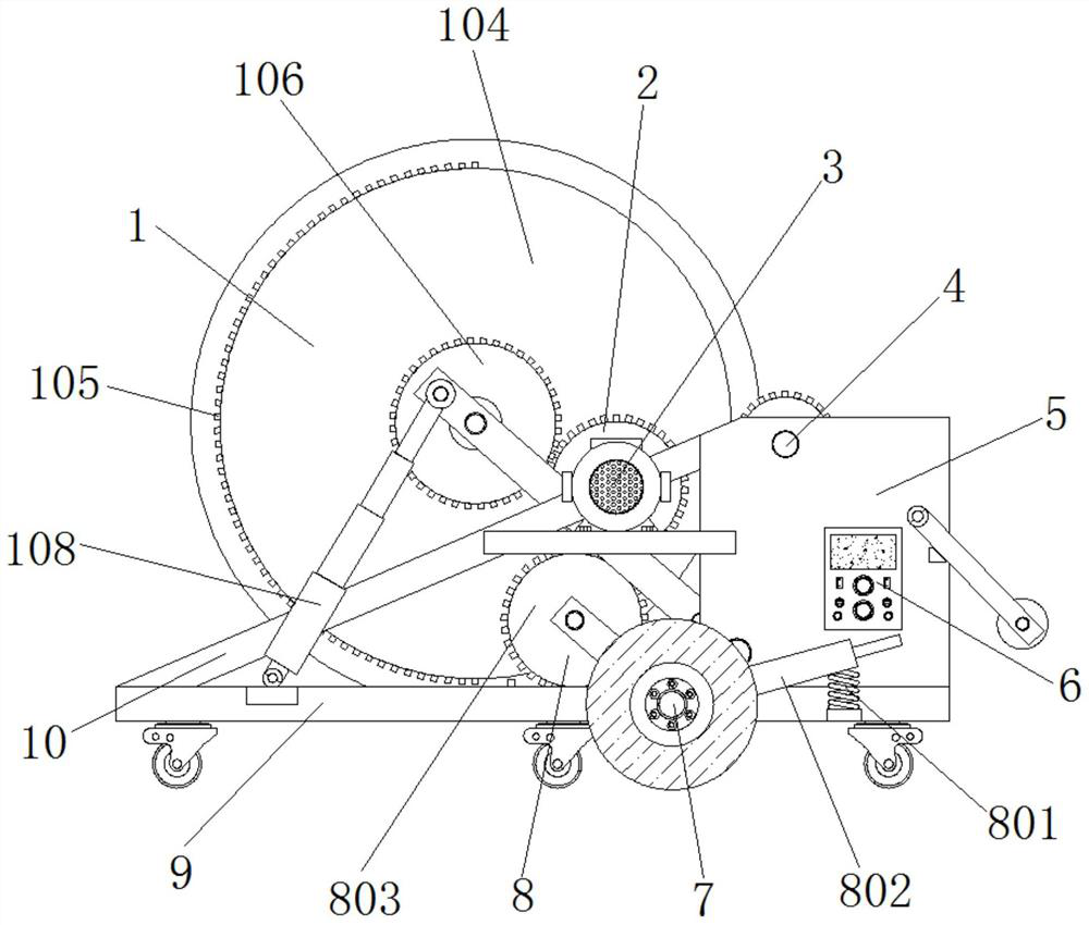
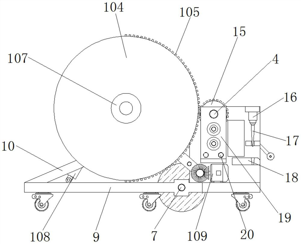
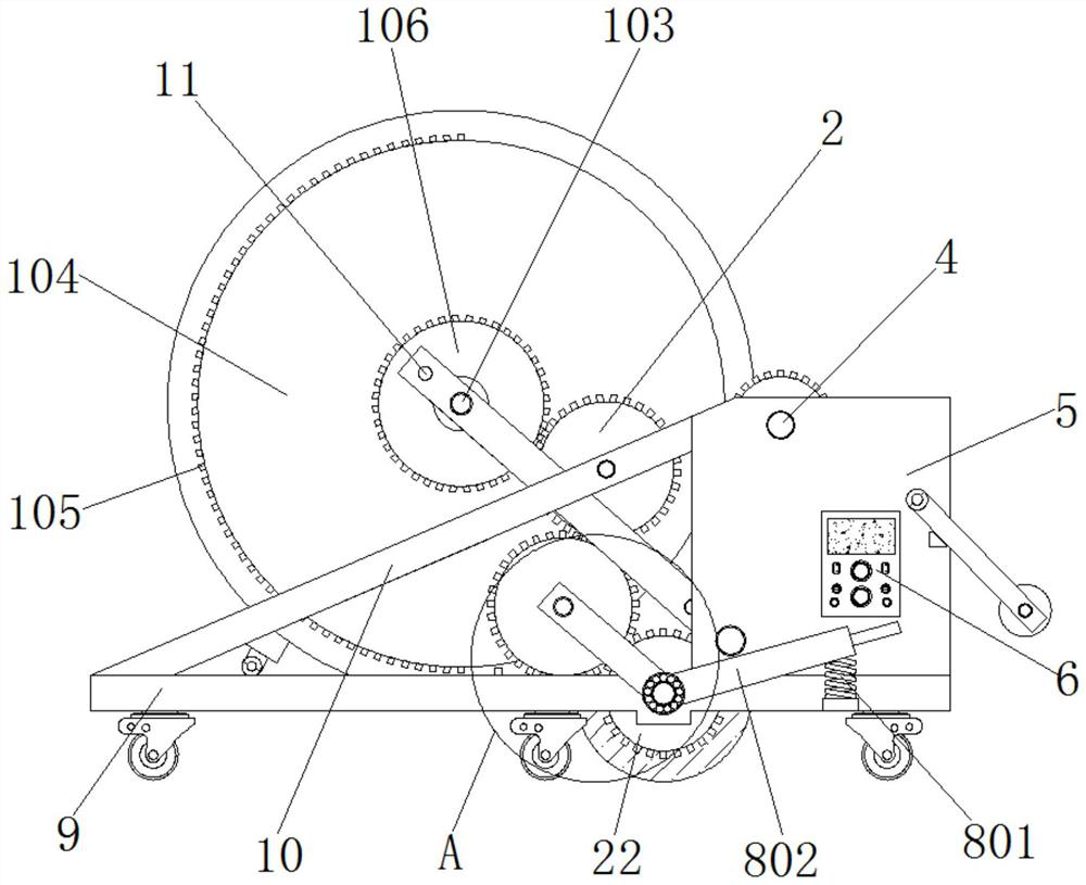
[0040] Example 1, such as Figure 1-6 As shown, before supporting the cable reel, the construction personnel first push the cable pay-off machine to the corresponding cable reel position, and make the cable reel located inside the U-shaped bottom plate 9, and then adjust the U-shaped bottom plate 9 position, so that the two groups of clamping round tables 107 are located outside the center of the two ends of the cable tray, and then adjust the positions of the semicircular racks 105 on the two groups of discs 104, so that the two groups of semicircular racks 105 alternate with the corresponding Driven by the driven gear 15 and the second auxiliary gear 25, the driving device 109 is controlled by the control panel 6 to drive the first rotating rod 101 to rotate, forcing the two groups of strip plates 102 to move toward each other until the two groups of clamping round tables 107 are respectively inserted into the wires. In the holes at the center of both ends of the cable reel,...
Embodiment 2
[0041] Example 2, such as figure 1 , 2 , 3, 4, 6 and 9, when the cable is buried in a straight line, the construction personnel first place a part of the head end of the cable into the pre-buried pit, and the driving direction of the U-shaped bottom plate 9 is also the same as the straight line pre-buried The directions of the pits are the same. At this time, the construction personnel can manually press down the end of the L-shaped movable rod 802 close to the control panel 6, the return spring 801 is shortened by force, and the connecting gear 803 rotates with the second rotating rod 7 as the axis, so that the connecting gear 803 meshes with the driving gear 2 and the driven gear 22 respectively, and then controls the servo motor 3 to drive the driving gear 2 to rotate, and utilizes the transmission connection of the driving gear 2, the connecting gear 803 and the driven gear 22 to drive the second rotating rod 7 to stabilize at a constant speed Rotate to drive the whole pa...
PUM
 Abstract
Description
Claims
Application Information
 - R&D
- Intellectual Property
- Life Sciences
- Materials
- Tech Scout
- Unparalleled Data Quality
- Higher Quality Content
- 60% Fewer Hallucinations
Browse by: Latest US Patents, China's latest patents, Technical Efficacy Thesaurus, Application Domain, Technology Topic, Popular Technical Reports.
© 2025 PatSnap. All rights reserved.Legal|Privacy policy|Modern Slavery Act Transparency Statement|Sitemap|About US| Contact US: help@patsnap.com


