Protective device for elevator hoistway
A technology of protective devices and elevator shafts, which is applied in the direction of transportation and packaging, lifting equipment in mines, elevators, etc., can solve problems such as user injuries, safety accidents, and no protective measures for elevator shafts, so as to reduce frictional noise, fixed tight effect
- Summary
- Abstract
- Description
- Claims
- Application Information
AI Technical Summary
Problems solved by technology
Method used
Image

Examples
Embodiment 1
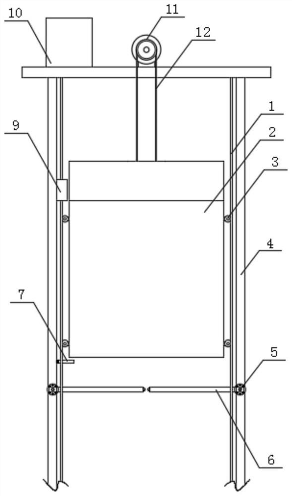
[0037] Such as figure 1 and Figure 6 As shown, a protective device for an elevator shaft includes a hoistway main body 4, a hoist 11 is installed above the hoistway main body 4, a car 2 is installed inside the hoistway main body 4, and the top of the car 2 is fixedly connected with a rope 12;
[0038] A starting pole 7 is installed below the side of the car 2 close to the leveling sensor 9, and a protective mechanism 6 is installed at the intersection of the bottom of the starting pole 7 and the hoistway main body 4;
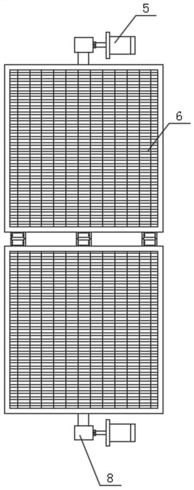
[0039] A transmission mechanism 5 is installed at the intersection of the protection mechanism 6 and the hoistway main body 4. The protection mechanism 6 is composed of a limit plate 61, a frame 62, a first pulley 63 and a protection net 64. The first pulley 63 is installed above the frame 62. The first pulley 63 is fixedly connected with the frame 62 by bolts, the protective net 64 is arranged inside the frame 62, the limit plate 61 is installed below the fra...
Embodiment 2
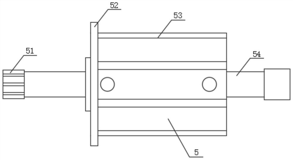
[0043] Such as image 3As shown, the transmission mechanism 5 is composed of a limit rod 51, a fixed plate 52, a cylinder assembly 53 and a transmission shaft 54. There is a sealing shaft, and the fixed disk 52 is installed on one end of the cylinder assembly 53. The fixed disk 52 is a disc-shaped structure. The side of the fixed disk 52 close to the cylinder assembly 53 is equipped with several screw rods and limit rods along the circumferential direction of the fixed disk 52. 51 is installed on the end of the transmission shaft 54 close to the fixed plate 52, and the connection mode between the limit rod 51 and the transmission shaft 54 is fixed by spot welding.
[0044] During specific use, when the transmission mechanism 5 is powered on, the cylinder assembly 53 drives the transmission shaft 54 to move, so that the transmission shaft 54 drives the limit rod 51 to move, so that the limit rod 51 can be separated from the limit disc 61, so that It is possible to make...
Embodiment 3
[0046] Such as Figure 7 As shown, the starting pole 7 is composed of a second pulley 71, a first connecting plate 72, a connecting piece 73, a first return spring 74, a fastener 75 and a cross bar 76, and the connecting piece 73 is installed on the first connecting plate 72. On one side, the first return spring 74 is installed under the first connecting plate 72, the cross bar 76 is installed under the first return spring 74, and the fastener 75 is installed at the intersection of the cross bar 76 and the first return spring 74 , the second pulley 71 is mounted on the end of the cross bar 76 away from the fastener 75 .
[0047] During specific use, when the first return spring 74 inside the start support rod 7 drives the start support rod 7 to rotate downward under the action of the car 2, the first return spring 74 accumulates energy, and when the car 2 and the start support rod 7 interact with each other When separating, when the first return spring 74 has no downward forc...
PUM
 Abstract
Description
Claims
Application Information