
Metal prefabricated pavement slab structure and prefabricated pavement

A board structure and metal technology, applied to roads, roads, special pavements, etc., can solve the problems of inability to recycle and reuse, low stability, etc., and achieve the effect of improving construction and repair efficiency, light weight, and quick installation

Pending Publication Date: 2022-01-28
SICHUAN HONGHUA PETROLEUM EQUIP
View PDF5 Cites 0 Cited by
  • Summary
  • Abstract
  • Description
  • Claims
  • Application Information

AI Technical Summary

Problems solved by technology

Prefabricated road slabs are installed by splicing, but after splicing, the overall stability is still not high, so the current practice is to use tensioned steel bars to apply a certain prestress to make the tensile area of ​​the pavement bear compressive stress in advance, so as to improve the prefabricated road surface. The overall tensile strength of the road slab is formed. The current prefabricated road slabs form permanent facilities after the construction is completed, that is, they cannot be recycled and reused after the construction is completed. There is no prefabricated pavement with high strength and easy recycling

Method used


Image

  • Metal prefabricated pavement slab structure and prefabricated pavement
  • Metal prefabricated pavement slab structure and prefabricated pavement
  • Metal prefabricated pavement slab structure and prefabricated pavement

Examples


Embodiment 1

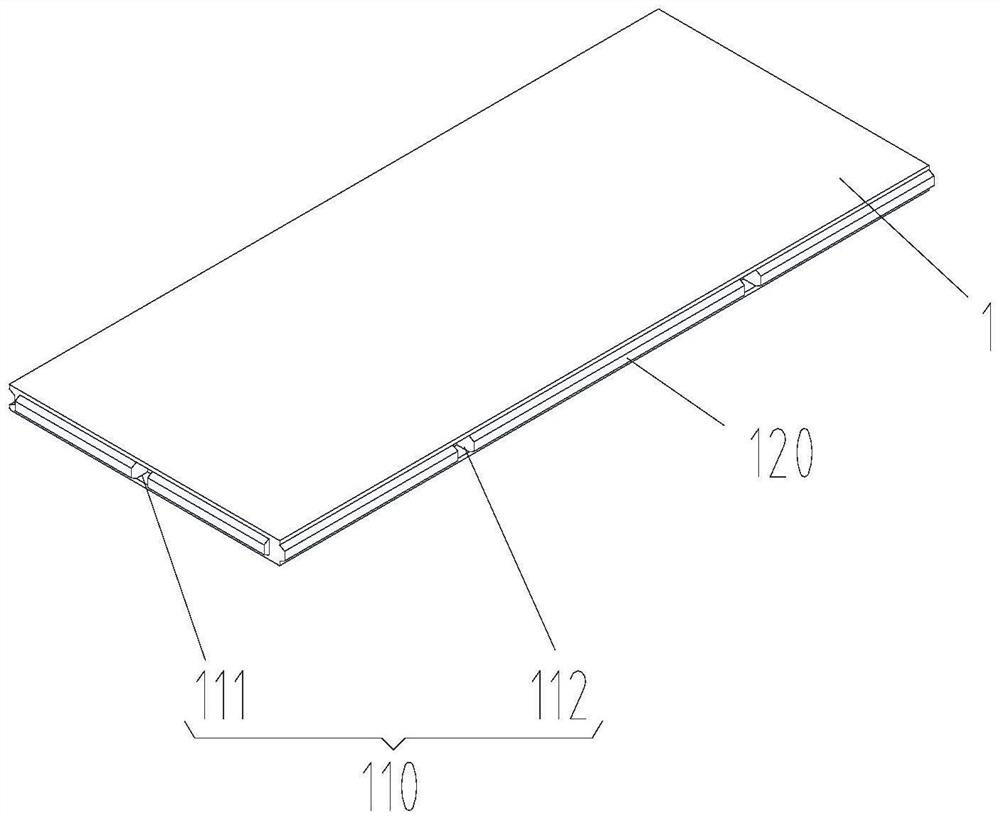
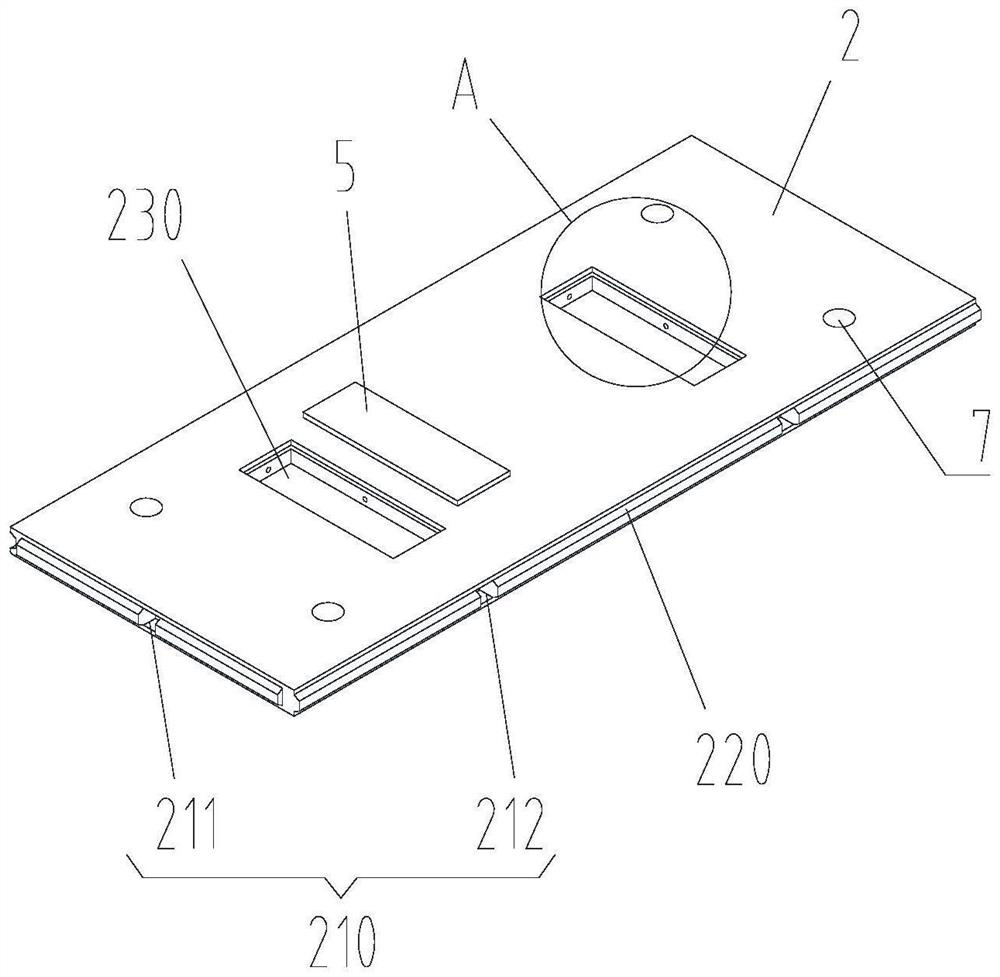
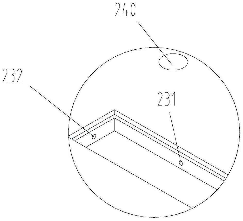
[0032] Such as Figure 1-Figure 3As shown, a metal prefabricated path panel structure provided by the embodiment of the present invention includes a first plate body 1 and a second plate body 2 made of metal materials that can be spliced ​​with each other; The first channel 110 of a plate body 1, the edge of the first plate body 1 is provided with a first groove 120; the second plate body 2 is provided with a second channel corresponding to the first channel 110 and extending in the same direction Hole 210, the edge of the second plate 2 is provided with a second rebate 220 that matches the first rebate 120; the upper side of the second plate 2 is provided with an anchor reserved groove for loading the anchor 3 230 , the second hole 210 passes through the anchor reserved groove 230 , so that the second hole 210 forms a perforation on the side wall of the anchor reserved groove 230 . Both the above-mentioned first plate body 1 and the second plate body 2 are made of metal mate...

Embodiment 2

[0034] Such as Figure 4 , different from Embodiment 2, the first hole 110 and the second hole 210 in this embodiment are arranged along the width direction of the first board body 1 or the second board body 2, that is, they are all longitudinally arranged correspondingly, but the first The plate body 1 is also provided with a first left oblique tunnel 113 and / or a first right oblique tunnel 114 . When the first left oblique tunnel 113 and the first right oblique tunnel 114 are both provided, the first left oblique tunnel 113 and the first right oblique tunnel 114 intersect, and the staggered stretching of this oblique direction can improve the local plate body Excellent interlocking performance, improve local integrity, and can effectively absorb and buffer omnidirectional impact loads.

Embodiment 3

[0036] refer to Figure 1 to Figure 3 , the difference from Embodiment 1 or 2 is that the above-mentioned first tunnel 110 includes a first transverse tunnel 111 and a first longitudinal tunnel 112 . The first transverse hole 111 extends along the length direction of the first plate 1 ; the first longitudinal hole 112 extends along the width of the first plate 1 . The second tunnel 210 includes a second transverse tunnel 211 and a second vertical tunnel 212 . The second transverse hole 211 extends along the length direction of the second plate body 2 ; the second longitudinal hole 212 extends along the width direction of the second plate body 2 . The first transverse hole 111 is parallel to the second transverse hole 211 ; the first longitudinal hole 112 corresponds to the second longitudinal hole 212 . The first transverse tunnel 111, the first longitudinal tunnel 112, the second transverse tunnel 211 and the second longitudinal tunnel 212 are arranged in this way, that is,...


PUM


Abstract

The invention relates to road engineering facilities, in particular to a metal prefabricated pavement slab structure and a prefabricated pavement. The metal prefabricated pavement slab structure comprises a first slab body and a second slab body which are made of metal materials; a first hole channel penetrating through the first slab body is formed in the first slab body, and a first rabbet is formed in the edge of the first slab body; the second slab body is provided with a second hole channel which corresponds to the first hole channel and extends in the same direction as the first hole channel, and the edge of the second slab body is provided with a second rabbet matched with the first rabbet; and an anchorage device reserved groove used for containing an anchorage device is formed in the upper side of the second slab body, and the second hole channel passes through the anchorage device reserved groove, so that the second hole channel forms a through hole in the side wall of the anchorage device reserved groove. By adopting the metal prefabricated pavement slab structure, the metal prefabricated pavement slab structure not only has more advantages in quality and strength compared with a concrete prefabricated slab, but also can be flexibly disassembled and assembled, that is, the metal prefabricated pavement slab structure can be quickly assembled, disassembled and recycled under the condition that a temporary pavement needs to be built and laid, and can be reused as equipment.

Description

technical field [0001] The invention relates to road engineering equipment, in particular to a metal prefabricated road panel structure and a prefabricated road surface. Background technique [0002] In the current social development demand environment, the high requirements for the quality and construction speed of traffic roads are becoming more and more obvious, so prefabricated road panels appear. Prefabricated road panels are pre-manufactured in factories and installed on site. Prefabricated road slabs are installed by splicing, but after splicing, the overall stability is still not high, so the current practice is to use tensioned steel bars to apply a certain prestress to make the tensile area of ​​the pavement bear compressive stress in advance, so as to improve the prefabricated road surface. The overall tensile strength of the road slab is formed. The current prefabricated road slabs form permanent facilities after the construction is completed, that is, they canno...

Claims


Application Information

Patent Timeline
Patent Type & Authority Applications(China)
IPC IPC(8): E01C9/08
CPCE01C9/083Y02A30/60
Inventor 颜子敏于芳游青青杨琼
Owner SICHUAN HONGHUA PETROLEUM EQUIP
Learn More