A small diameter oil pipe plug

A tubing plug and small-diameter technology, which is applied in wellbore/well components, sealing/isolation, earthwork drilling and production, etc. It can solve the problems of low plugging success rate, small plugging force, and affecting plugging success rate, etc. , to achieve the effect of strong pressure resistance and large sealing force

Active Publication Date: 2022-08-02
大庆市润百利科技有限公司
View PDF0 Cites 0 Cited by
  • Summary
  • Abstract
  • Description
  • Claims
  • Application Information

AI Technical Summary

Problems solved by technology

[0003] However, when plugging a tubing with an inner diameter of 62 mm, the plug needs to pass through a channel of 45 mm or even smaller to reach the predetermined plugging position. Small diameter, however, the existing plugs generally have a high-pressure chamber and a low-pressure chamber, which first take up a lot of space and are not convenient to reduce the diameter of the plug, and secondly, because the plug needs to be reduced in diameter, the space for each part of the tool string in the plug is limited , which in turn makes it difficult to fix the slips well, causing the slips to fall off easily or the anchoring is unstable, and the positioning pin of the existing plug setting mechanism can push the piston cylinder upward after being cut, so the position is fixed only by means of The positioning pin, when the pressure difference in the cavity is too large, the positioning pin is easy to be cut off by mistake, which affects the success rate of sealing. Not only that, it mainly relies on hydraulic power to drive the piston cylinder to move, resulting in a small sealing force, which also affects the sealing Success rate
[0004] Due to the above reasons, there are few plugs that can meet the construction requirements at present, and the plugging success rate is low, so there is an urgent need for a new type of small-diameter tubing plug

Method used


Image

  • A small diameter oil pipe plug
  • A small diameter oil pipe plug
  • A small diameter oil pipe plug

Examples


Embodiment Construction

[0029] The technical solutions in the embodiments of the present invention will be clearly and completely described below with reference to the accompanying drawings in the embodiments of the present invention. Obviously, the described embodiments are only a part of the embodiments of the present invention, but not all of the embodiments. Based on the embodiments of the present invention, all other embodiments obtained by those of ordinary skill in the art without creative efforts shall fall within the protection scope of the present invention.

[0030] In order to make the above objects, features and advantages of the present invention more clearly understood, the present invention will be described in further detail below with reference to the accompanying drawings and specific embodiments.

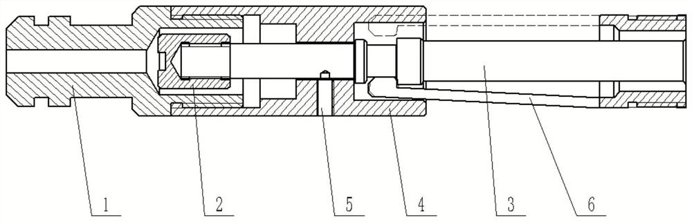
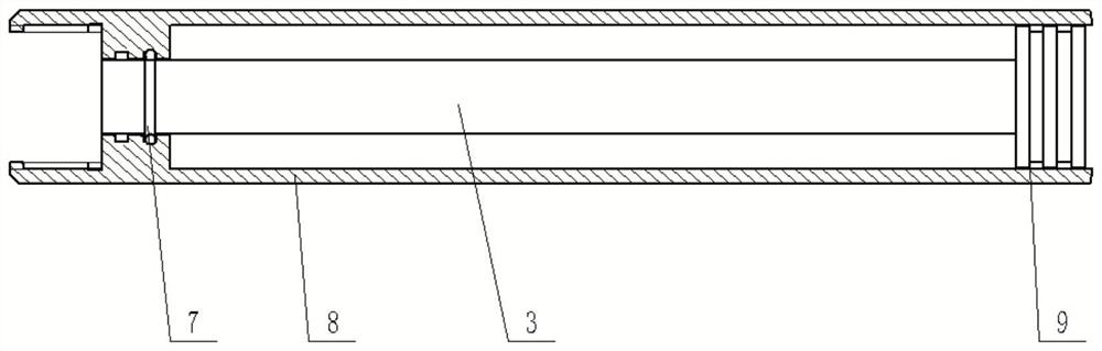
[0031] refer to Figure 1-5 , The present invention provides a small diameter oil pipe plug, which is used to temporarily block the inner channel of the oil pipe, which belongs to the w...


PUM


Abstract

The invention discloses a small-diameter oil pipe plug, which includes a start-up locking mechanism, the start-up locking mechanism includes a positioning pressure cap, the positioning pressure cap is provided with a mandrel, the mandrel does not completely come out of the positioning pressure cap, and the head end of the positioning pressure cap is detachable An elastic locking piece is connected; the pneumatic energy storage power mechanism includes a power push cylinder arranged at the head end of the elastic locking piece, and a piston push head is fixed on the mandrel; the positioning mechanism includes a wing plate assembly arranged at the head end of the power push cylinder, and the wing plate assembly is used for Position the small diameter oil pipe plug at the oil pipe coupling, the head end of the wing plate assembly is provided with a circlip assembly, the circlip assembly is used to make the mandrel slide in one direction, and the head end of the circlip assembly is provided with several circumferentially arranged The hinge slip; the sealing mechanism includes elastic seals, both ends of the elastic seals are provided with extruded parts, the mandrel runs through the two extruded parts and the elastic seals, the outer diameter of the device is not greater than 38mm, which can meet the current requirements Construction requirements, its blocking force is large, the pressure resistance is strong, and the blocking success rate is high.

Description

technical field [0001] The invention relates to the technical field of special pressure-operated auxiliary tools in oilfield major workover operations, in particular to a small-diameter tubing plug. Background technique [0002] At present, there are many kinds of special tools for plugging tubing under pressure in oilfield under pressure operation. In order to ensure that there is no leakage during the whole process of pipe string lifting and lowering, the tool string should be blocked step by step. The structure of the used occluder generally includes a slip mechanism, a sealing mechanism, a setting mechanism, a locking mechanism and a positioning mechanism sequentially connected from top to bottom. For the plug, the positioning mechanism is stuck at the tubing coupling, and the plug is positioned in the pipe string; if the plug is continued to be lifted up, the positioning pin in the setting mechanism is cut off, and the bottom hole liquid pushes the piston cylinder in th...

Claims


Application Information

Patent Timeline
Patent Type & Authority Patents(China)
IPC IPC(8): E21B33/1295
CPCE21B33/1295
Inventor 吕文学
Owner 大庆市润百利科技有限公司
Why Eureka
Try Eureka