Method for evaluating carbon dioxide injection profile of horizontal well

A carbon dioxide and evaluation method technology, which is applied in the direction of earthwork drilling, wellbore/well components, and production fluids, can solve the problems of difficult production of low-permeability reservoirs, achieve geological storage, high-efficiency geological storage, and delay breakthrough time Effect

Active Publication Date: 2022-01-28
INST OF ROCK & SOIL MECHANICS CHINESE ACAD OF SCI
View PDF5 Cites 2 Cited by
  • Summary
  • Abstract
  • Description
  • Claims
  • Application Information

AI Technical Summary

Problems solved by technology

[0004]Therefore, in view of the strong heterogeneity of low-permeability reservoirs in my country, when CO2 is injected into horizontal wells, it is easy to break through in high-permeability reservoirs. Ineffective circulation in injection and production wells leads to major bottlenecks such as difficult production of low-permeability reservoirs

Method used


Image

  • Method for evaluating carbon dioxide injection profile of horizontal well
  • Method for evaluating carbon dioxide injection profile of horizontal well
  • Method for evaluating carbon dioxide injection profile of horizontal well

Examples


Embodiment 1

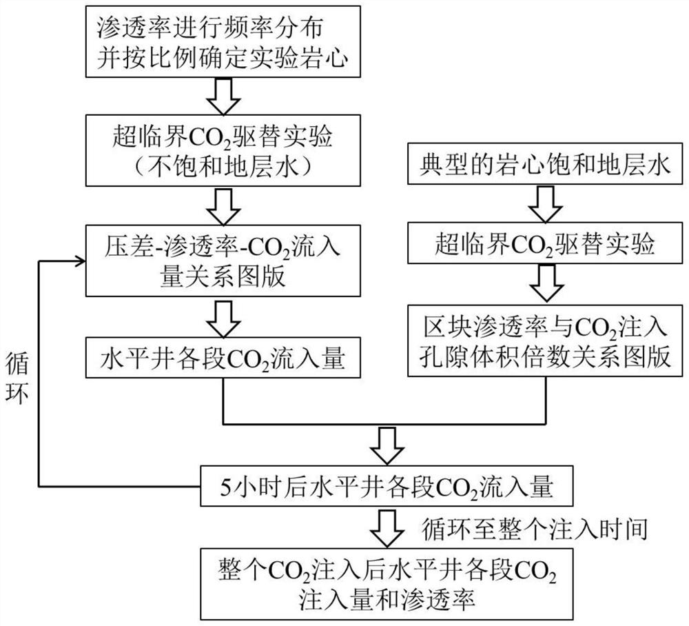
[0031] according to figure 2 It can be seen that a method for evaluating the carbon dioxide injection profile of a horizontal well comprises the following steps:

[0032] (1) Determine the reservoir permeability distribution along the horizontal well according to the logging data, and determine the experimental core in proportion to the frequency distribution according to the permeability;

[0033] (2) Use the determined core (unsaturated formation water) to carry out supercritical carbon dioxide (CO2) 2 )

[0034] Flooding experiments to obtain supercritical carbon dioxide (CO 2 ) injection volume;

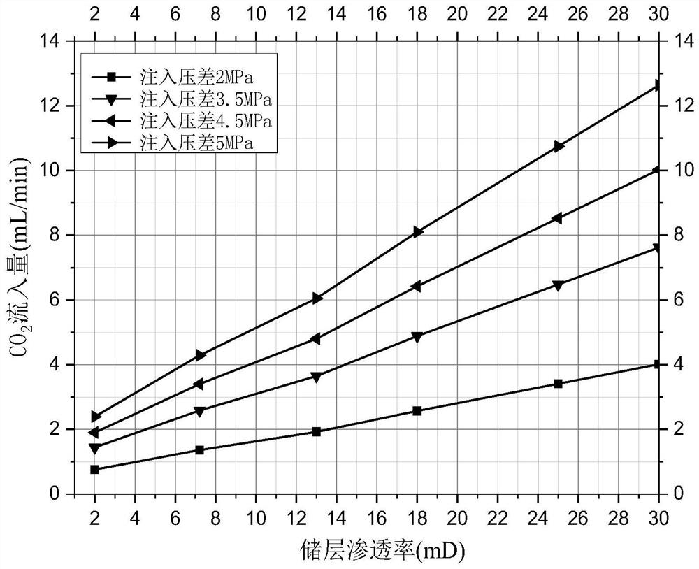
[0035] (3) Draw the pressure difference-permeability-CO of the reservoir in the research block through the displacement experiment results 2 Inflow relationship chart;

[0036] (4) For carbon dioxide injection (CO 2 ) horizontal wells, in this step, in order to realize the rationality of the experimental simulation, the similarity criterion is used to perform equivalent tr...

Embodiment 2

[0061] to inject CO 2 Take the displacement exploitation of an oil field as an example, to get its horizontal well CO 2 Injection profile, which includes the following steps:

[0062] (1) Assume that according to the completion logging data of the horizontal well drilled in the oil field, the permeability range is 0.2-252mD, and then according to the permeability difference of the drilled well, the permeability of the core to be tested is 0.2mD, 4mD, 8mD, 12mD , 16mD, 20mD, 24mD, 28mD...252mD;

[0063] (2) Using the rock core determined in step (1), carry out supercritical CO 2 Displacement experiments, assuming that the obtained experimental results are used to obtain the pressure difference-permeability-CO 2 Inflow relationship chart, such as figure 1 shown;

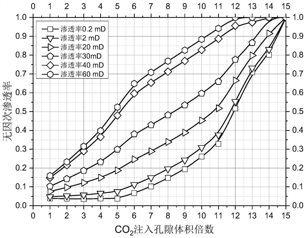
[0064] (3) Use the typical cores in this block to saturate the formation water, and then carry out the displacement experiment to obtain the CO during the experiment. 2 Inject the relationship between pore volume...


PUM


Abstract

The invention discloses a method for evaluating a carbon dioxide injection profile of a horizontal well. The method comprises the following steps of (1) determining an experimental rock core according to a frequency distribution proportion and reservoir permeability distribution of horizontal well distribution; (2) implementing a supercritical CO2 displacement experiment by using the rock core, and drawing a pressure difference-permeability-CO2 inflow chart of the research block reservoir; (3) carrying out a displacement experiment by utilizing typical core saturated formation water of the research block, and drawing a chart of permeability of the block and the CO2 injection pore volume times; (4) a CO2 injection horizontal well being selected, and the supercritical CO2 inflow amount under the injection pressure being obtained according to the pressure difference-permeability-CO2 inflow amount relation chart; (5) obtaining the permeability distribution of the horizontal section after the reaction according to the relation chart of the permeability of the block and the CO2 injection pore volume multiple; and (6) circulating to obtain the permeability of reservoir sections with different permeability after CO2 is injected. The method is easy to implement, easy and convenient to operate and wide in application range, and evaluation of the CO2 injection profiles of the horizontal wells of different reservoir types is achieved.

Description

technical field [0001] The invention belongs to the technical field of carbon dioxide geological utilization and sequestration, in particular to a horizontal well carbon dioxide (CO 2 ) injection profile evaluation method, applicable to horizontal well CO 2 Injection effect evaluation and horizontal well CO 2 Injection adjustment to improve CO 2 Displacement efficiency and geological storage capacity. Background technique [0002] with CO 2 The increase in greenhouse gas emissions has brought a series of global environmental problems, CO 2 Emission reduction has become a hot issue of human concern. Atmospheric CO 2 The average concentration has increased from 280ppm before the industrial revolution (1750) to the current 380ppm. If no measures are taken, it will reach 1100ppm in 2100. Therefore, CO 2 Emission reduction has become a major challenge facing mankind. Human beings cannot get rid of the use of fossil energy in the short term. So, CO 2 Capture and geologi...

Claims


Application Information

Patent Timeline
Patent Type & Authority Applications(China)
IPC IPC(8): E21B43/16E21B49/00E21B47/00E21F17/16
CPCE21B43/164E21B49/00E21B47/00E21F17/16Y02P90/70
Inventor 谭永胜李琦徐亮徐丽风余涛
Owner INST OF ROCK & SOIL MECHANICS CHINESE ACAD OF SCI
Why Eureka
Try Eureka