Electrical test wire clamp structure

An electrical test and wire clip technology, which is applied to the casing of the measuring device, etc., can solve the problems of inconspicuousness, short-circuiting of different terminal circuits, hazards, etc., and achieve the effects of reducing electric shock, simplifying the structure, and reducing scratches.

Pending Publication Date: 2022-01-28
SHENZHEN POWER SUPPLY BUREAU
View PDF8 Cites 0 Cited by
  • Summary
  • Abstract
  • Description
  • Claims
  • Application Information

AI Technical Summary

Problems solved by technology

[0002] In the prior art, the clamp structure used for conventional electrical tests usually uses the end clamp part to contact the equipment to realize electrical connection. Due to the unreasonable design of the existing electrical test clamp structure, it is easy to cause gaps between different terminals during the installation process. The circuit is short-circuited, and there is a safety hazard of protection malfunction
[0003] At the same time, in order to ensure good contact, the clamping part of the electrical test wire clamp is mostly designed in a jagged shape, which is easy to scratch the conductive surface of the equipment when connected to the conductor surface of the electrical equipment; in addition, the structure of the conventional electrical test wire clamp is not convenient for storage. Leakage is not easy to detect and may cause certain harm

Method used


Image

  • Electrical test wire clamp structure
  • Electrical test wire clamp structure
  • Electrical test wire clamp structure

Examples


Embodiment Construction

[0021] The following will clearly and completely describe the technical solutions in the embodiments of the present invention with reference to the accompanying drawings in the embodiments of the present invention. Obviously, the described embodiments are only some, not all, embodiments of the present invention. Based on the embodiments of the present invention, all other embodiments obtained by persons of ordinary skill in the art without creative efforts fall within the protection scope of the present invention.

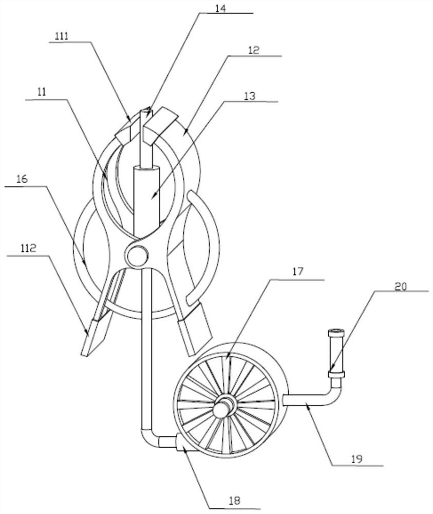
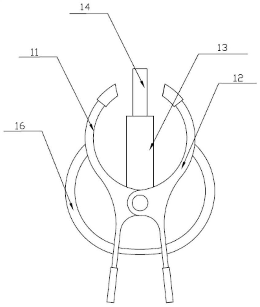
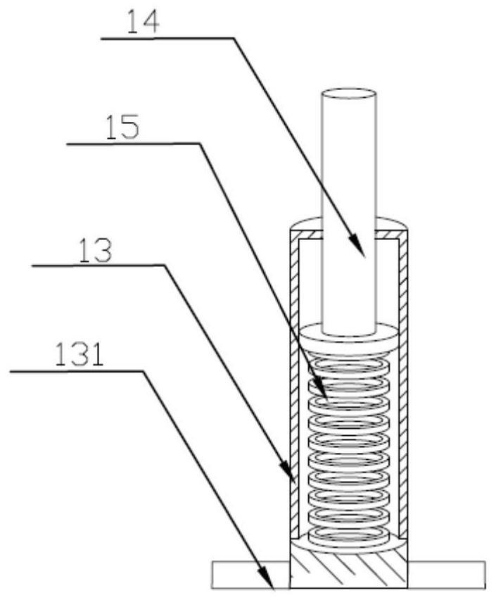
[0022] Such as Figure 1-Figure 4 Shown is Embodiment 1 of the electric test wire clip structure of the present invention.

[0023] The electrical test wire clip structure in the present embodiment comprises: seat cover 13, and seat cover 13 is hollow tubular structure; The first clamping piece 11 and the second clamping piece 12 form a jaw structure. The clamping part is provided with a pressing assembly 16; a detachable conductive rod 14 installed in the seat c...


PUM


Abstract

The invention discloses an electrical test wire clamp structure, and the structure comprises: a seat sleeve which is of a hollow tubular structure; a clamping part which is arranged outside the seat sleeve, wherein a pressing assembly is arranged on the clamping part; a conducting rod detachably installed in the socket sleeve and a connecting wire detachably connected to the conducting rod, wherein a connecting plug is arranged on an end of the connecting wire; a wire winding assembly used for storing the connecting wire, wherein a miniature anti-creeping switch connected to the wire winding assembly and used for detecting whether the connecting wire leaks electricity or not, the miniature anti-creeping switch is electrically connected with the connecting wire, and the conducting rod, the connecting wire, the miniature anti-creeping switch and the connecting plug form an electrical path. By implementing the electrical test wire clamp structure, the safety risks of electric shock and short circuit in the use process can be reduced; scratches of the clamping part on the surface of the electrical equipment are reduced, and the structure is simple, safe and reliable.

Description

technical field [0001] The invention relates to the technical field of electrical testing, in particular to an electrical testing wire clip structure. Background technique [0002] In the prior art, the clamp structure used for conventional electrical tests usually uses the end clamp part to contact the equipment to realize electrical connection. Due to the unreasonable design of the existing electrical test clamp structure, it is easy to cause gaps between different terminals during the installation process. The circuit is short-circuited, and there is a potential safety hazard of protection malfunction. [0003] At the same time, in order to ensure good contact, the clamping part of the electrical test wire clamp is mostly designed in a jagged shape, which is easy to scratch the conductive surface of the equipment when connected to the conductor surface of the electrical equipment; in addition, the structure of the conventional electrical test wire clamp is not convenient ...

Claims


Application Information

Patent Timeline
Patent Type & Authority Applications(China)
IPC IPC(8): G01R1/04
CPCG01R1/04
Inventor 徐刚傅川岳池方仁何小龙张繁廖伟兴王凯陈伟平麦彦杰张杰张庆
Owner SHENZHEN POWER SUPPLY BUREAU
Why Eureka
Try Eureka