Analog chip circuit winding method

A winding method and analog chip technology, applied in electrical digital data processing, special data processing applications, instruments, etc., can solve the problems of poor winding results, no company use, slow calculation speed, etc., and achieve the effect of fast wiring speed

Pending Publication Date: 2022-01-28
苏州复鹄电子科技有限公司
View PDF0 Cites 0 Cited by
  • Summary
  • Abstract
  • Description
  • Claims
  • Application Information

AI Technical Summary

Problems solved by technology

The calculation speed of the winding tool for analog chips is slow, the winding result is poor, and basically no company uses it

Method used


Image

  • Analog chip circuit winding method

Examples


Embodiment Construction

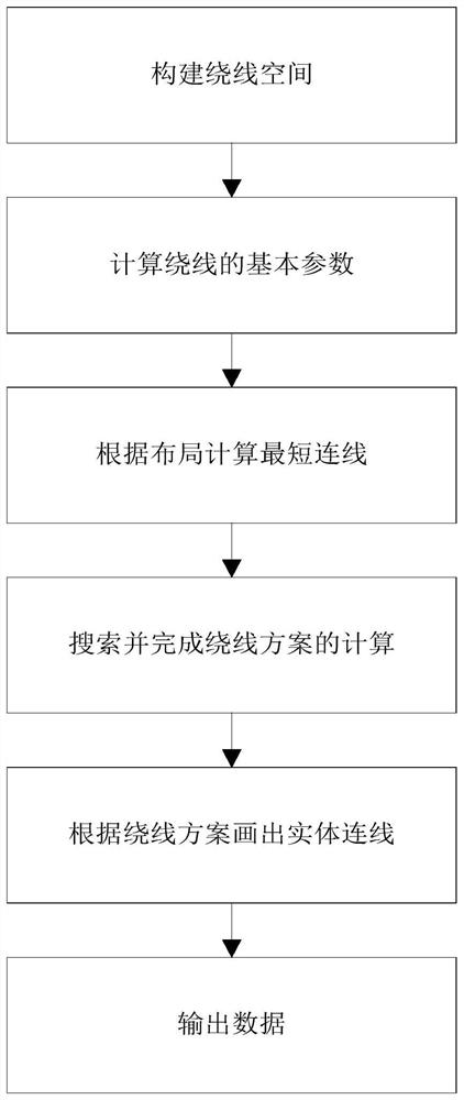
[0022] Such as figure 1 Shown: the analog chip circuit winding method of this embodiment, including steps;

[0023] S1. Divide the winding area in multiple winding layers, and find out the area that can be wired in the metal wiring layer:

[0024] S101. Specifically, for example, it is planned to wind on Metal1 and Metal2, and Metal is the metal wiring layer. On the Metal and Metal2 of the chip, according to the existing space occupation, the winding area (generally a rectangle) is divided to form a walkable The area of ​​the line is planned according to the process rules, and Metal performs winding according to the plan.

[0025] Because different processes stipulate different spacing distance requirements for different widths of Metal. The area that can be routed in the routing area will be affected differently by the devices and routings in the adjacent areas on the side. Therefore, it is necessary to calculate the redundant space between the routing area and adjacent dev...


PUM


Abstract

The invention relates to the technical field of analog chips, in particular to an analog chip circuit winding method, which comprises the following steps of: constructing a winding space, calculating basic parameters of winding, calculating a shortest connecting line according to layout, searching and finishing calculation of a winding scheme, drawing an entity connecting line according to the winding scheme, outputting data and the like, thereby automatically finishing a block-level connecting line. The wiring speed is high, the layout is reasonable, and the DRC accuracy and the connectivity rate are high.

Description

technical field [0001] The invention relates to the field of analog chips, in particular to a circuit winding method for an analog chip. Background technique [0002] The winding tools of existing commercial products are mainly aimed at digital chip algorithms, which are relatively mature. The calculation speed of the winding tool for analog chips is slow, the winding result is poor, and basically no company uses it. The automation tools of analog chips have been unresolved problems, and the winding algorithm of analog chips is one of the major problems. Contents of the invention [0003] In view of this, the purpose of the present invention is to provide an analog chip circuit winding method, which can automatically complete the wiring of the analog chip after the design and layout of the analog chip are completed. [0004] The analog chip circuit winding method of the present invention comprises the steps of: [0005] S1. Divide the winding area in multiple winding la...

Claims


Application Information

Patent Timeline
Patent Type & Authority Applications(China)
IPC IPC(8): G06F30/394
CPCG06F30/394
Inventor 张玮郭巍伟张静肖蓝碧健
Owner 苏州复鹄电子科技有限公司
Why Eureka
Try Eureka