
Bias and gain adjustable radio frequency amplifier

A radio frequency amplifier and error amplifier technology, applied in the field of radio frequency amplifiers, can solve the problems of non-adjustable gain-power-energy-efficiency ratio affecting energy-efficiency efficiency, lack of variable gain, non-extensible adjustment of the dynamic range of received signals, etc., so as to improve the dynamic range of reception. , the effect of extending the receiving dynamic range and improving the efficiency of gain and power consumption energy efficiency ratio

Pending Publication Date: 2022-01-28
SHANGHAI HUAHONG GRACE SEMICON MFG CORP
View PDF0 Cites 0 Cited by
  • Summary
  • Abstract
  • Description
  • Claims
  • Application Information

AI Technical Summary

Problems solved by technology

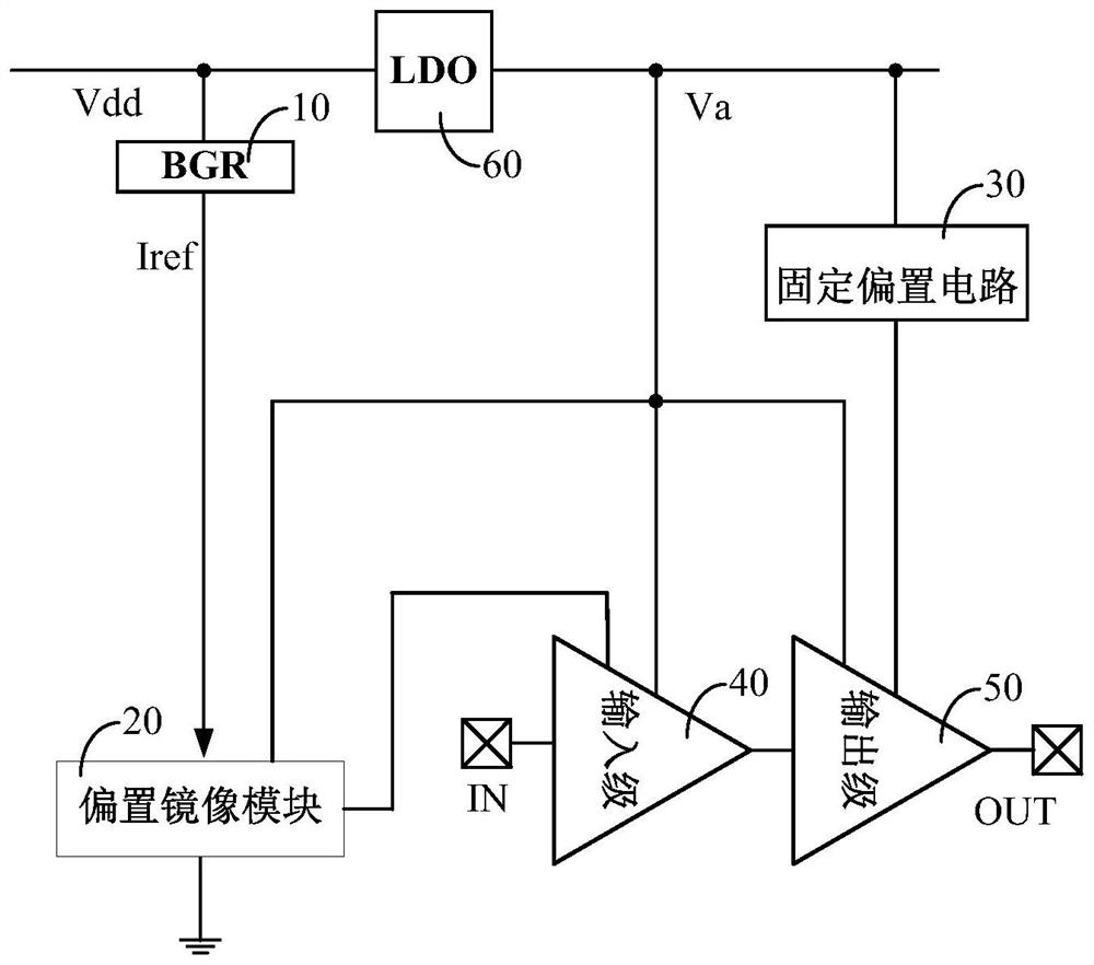
[0005] Depend on figure 1 It can be seen that both the RF input stage 40 and the RF output stage 50 use fixed bias circuits, their power consumption and gain are also fixed, and there is no variable gain. fixed not expandable

Method used


Image

  • Bias and gain adjustable radio frequency amplifier
  • Bias and gain adjustable radio frequency amplifier
  • Bias and gain adjustable radio frequency amplifier

Examples


Embodiment Construction

[0029] The embodiments of the present invention will be described below through specific examples and in conjunction with the accompanying drawings, and those skilled in the art can easily understand other advantages and effects of the present invention from the contents disclosed in this specification. The present invention can also be implemented or applied through other different specific examples, and various details in this specification can also be modified and changed based on different viewpoints and applications without departing from the spirit of the present invention.

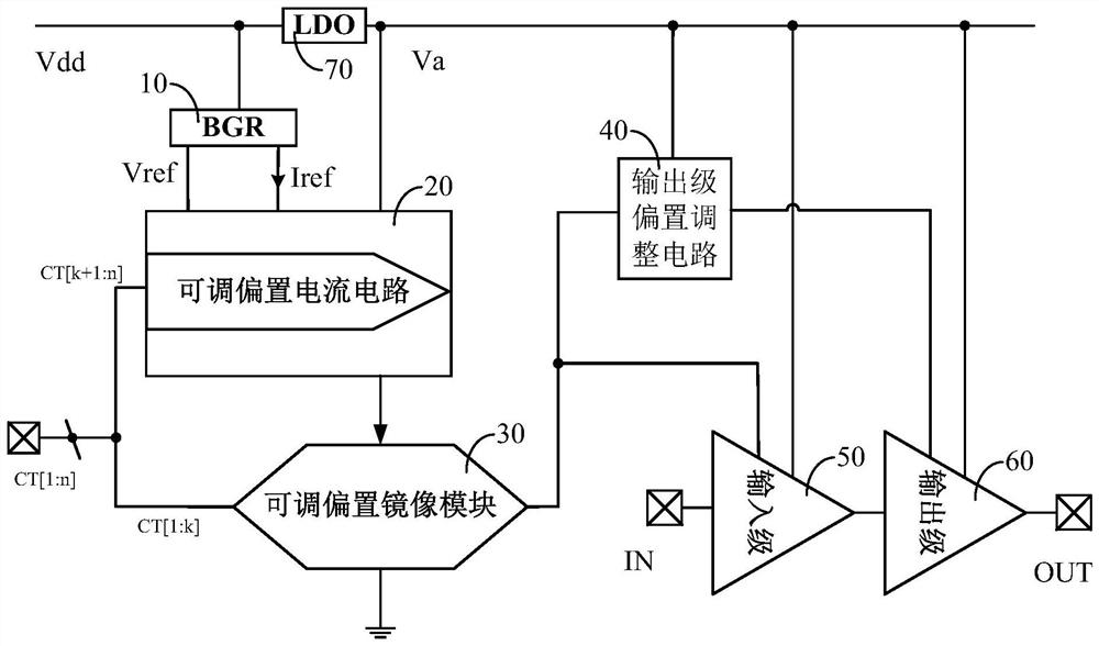
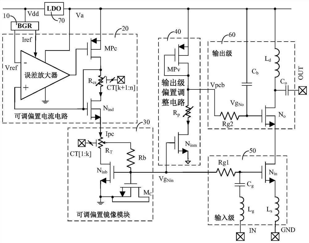
[0030] figure 2 It is a circuit structure diagram of a radio frequency amplifier with adjustable bias and gain according to the present invention, image 3 It is a circuit structure diagram of a radio frequency amplifier with adjustable bias and gain in a specific embodiment of the present invention. like figure 2 and image 3 As shown, the present invention is a radio frequency amplifier with ...


PUM


Abstract

The invention discloses a bias and gain adjustable radio frequency amplifier, comprising: a band-gap reference which is used for generating a reference current and voltage and outputting the reference current and voltage to an adjustable bias current circuit; the adjustable bias current circuit which is used for converting the reference current and voltage into an adjustable bias current required by an adjustable bias mirror image module under the control of an (n-k)-bit digital control signal; the adjustable bias mirror image module which is used for converting the adjustable bias current into an adjustable bias voltage required by an output stage bias adjusting circuit and an input stage under the control of a k-bit digital control signal; the output stage bias adjustment circuit which is used for converting the adjustable bias voltage into an output stage bias voltage required by an output stage; a radio frequency input and output stage which is used for carrying out cascade amplification on a radio frequency input signal through the input and output stages to obtain a radio frequency output signal under the control of an input and output stage bias voltage; and a low dropout regulator circuit.

Description

technical field [0001] The invention relates to a radio frequency amplifier, in particular to a radio frequency amplifier with adjustable offset and gain. Background technique [0002] As the key module of system signal reception, the power consumption and gain of amplifier are very important, which affect the minimum signal reception sensitivity and maximum signal reception capability, thus affecting the dynamic range and energy efficiency of system signal reception. Therefore, the amplifier is designed with adjustable bias power consumption and gain optimization to achieve adjustable gain. Adjust the bias according to the received signal strength to adjust the gain, which can improve the signal sensitivity and the maximum received signal strength, improve the dynamic range of the system, and optimize the gain function. Energy efficiency and extended battery life. [0003] like figure 1 As shown, a conventional RF amplifier includes a bandgap reference (BGR) 10 , a bias m...

Claims


Application Information

Patent Timeline
Patent Type & Authority Applications(China)
IPC IPC(8): H03F3/193H03F1/02H03G3/30
CPCH03F3/193H03F1/0205H03G3/3036
Inventor 戴若凡
Owner SHANGHAI HUAHONG GRACE SEMICON MFG CORP
Learn More