Key and keyboard
A button and keyboard technology, which is applied in the application field of magnetic sensors, can solve the problems of inconsistency in performance, poor experience, and errors in magnetic field strength detected by magnetic sensors, and achieve good performance consistency, good detection accuracy, and good user experience.
- Summary
- Abstract
- Description
- Claims
- Application Information
AI Technical Summary
Problems solved by technology
Method used
Image
Examples
no. 1 example
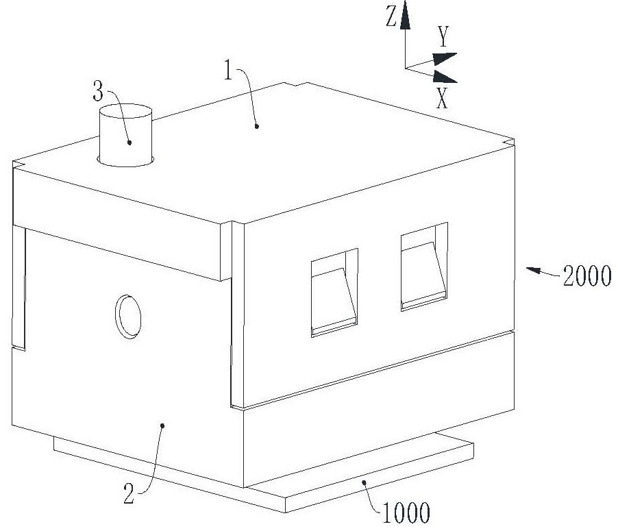
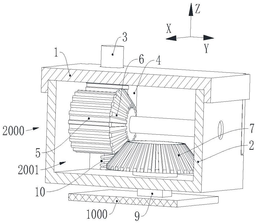
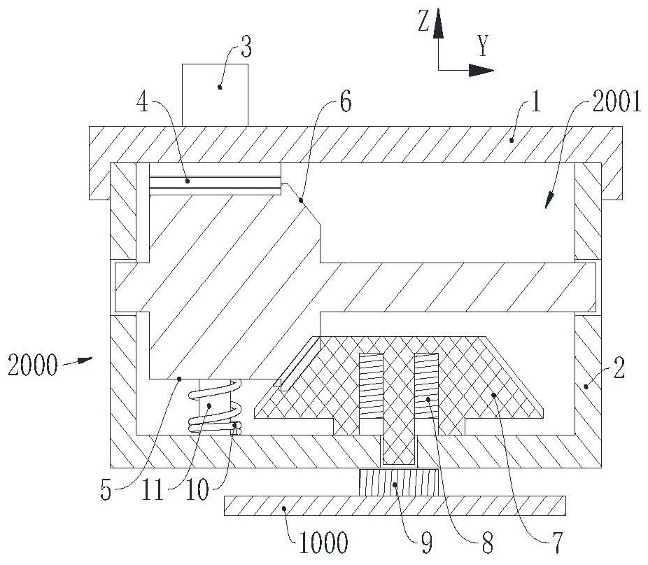
[0045] In this embodiment Figure 1 to Figure 3 A unified space Cartesian coordinate system (right-handed system) is adopted to represent the relative positional relationship between components, where the positive direction of the Z-axis is vertically upward.
[0046] Please refer to Figure 1 to Figure 3 , the keyboard of this embodiment includes an upper shell, a lower shell (not shown in the figure), a circuit board 1000 and a plurality of keys 2000 of this embodiment. On the positive side of the Z-axis of the shell, the upper shell and the lower shell are fixedly connected by screws. The upper shell and the lower shell form the first installation cavity. The combination of the upper shell, the lower shell and the circuit board 1000 can be set with reference to the existing keyboard , which will not be repeated here.
[0047] The button 2000 of this embodiment includes a cover body 1, a frame body 2, a key cap (not shown in the figure), a key shaft 3, a first rack 4, a fi...
no. 2 example
[0064] In this embodiment Figure 4 to Figure 6 A unified spatial Cartesian coordinate system (right-handed system) is adopted to represent the relative positional relationship between components, where the positive direction of the Z' axis is vertical upward.
[0065] Please refer to Figure 5 and Figure 6 The main structure of the keyboard in this embodiment is the same as that in the first embodiment, except that the key shaft 3' of the key 2000' is transmitted to the corresponding permanent magnet. The transmission connection of the key shaft 3' to the corresponding permanent magnet in this embodiment includes The key shaft 3', the second rack 12' and the second spur gear 13' that are transmitted in sequence, the permanent magnet is fixed on the negative end of the Z' axis of the second spur gear 13', and the permanent magnet and the second spur gear 13' The fixed cooperation method can be set with reference to the fixed cooperation method between the permanent magnet 8...
no. 3 example
[0074] In this embodiment Figure 7 to Figure 9 A unified spatial Cartesian coordinate system (right-handed system) is adopted to represent the relative positional relationship between the components, wherein the positive direction of the Z'' axis is vertically upward, and the direction of the Z'' axis in this embodiment is the first direction.
[0075] Please refer to Figure 7 to Figure 9 , the main structure of the keyboard in this embodiment is the same as that of the first embodiment, the difference lies in the transmission mode from the key shaft 3'' of the button 2000'' to the corresponding permanent magnet 8'', and the key shaft 3'' of this embodiment to the permanent magnet The transmission of the magnet 8 ″ adopts the cooperation of the spiral groove 171 ″ (an example of a spiral guide rail) and the boss 184 ″ (an example of a guide part) described later.
[0076] The keycap of this embodiment, the integrally formed key shaft 3'', the connecting plate 16'' and the t...
PUM
 Abstract
Description
Claims
Application Information
 - R&D
- Intellectual Property
- Life Sciences
- Materials
- Tech Scout
- Unparalleled Data Quality
- Higher Quality Content
- 60% Fewer Hallucinations
Browse by: Latest US Patents, China's latest patents, Technical Efficacy Thesaurus, Application Domain, Technology Topic, Popular Technical Reports.
© 2025 PatSnap. All rights reserved.Legal|Privacy policy|Modern Slavery Act Transparency Statement|Sitemap|About US| Contact US: help@patsnap.com


