Relay detection device capable of improving detection efficiency

A detection device and detection efficiency technology, which is applied in the direction of transportation and packaging, circuit breaker testing, conveyor objects, etc., can solve the problems of slow detection speed of relays, and achieve the goals of avoiding slow detection speed, improving detection efficiency, and improving detection efficiency Effect

Pending Publication Date: 2022-02-01
STATE GRID JIANGSU ELECTRIC POWER CO LTD MAINTENANCE BRANCH +1
View PDF5 Cites 0 Cited by
  • Summary
  • Abstract
  • Description
  • Claims
  • Application Information

AI Technical Summary

Problems solved by technology

[0004] The present invention provides a relay detection device capable of improving the detection efficiency, which has the beneficial effect of improving the detection efficiency of the relay, and solves the problem of slow detection speed of the relay mentioned in the above-mentioned background technology

Method used


Image

  • Relay detection device capable of improving detection efficiency
  • Relay detection device capable of improving detection efficiency
  • Relay detection device capable of improving detection efficiency

Examples


Embodiment 1

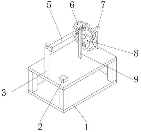
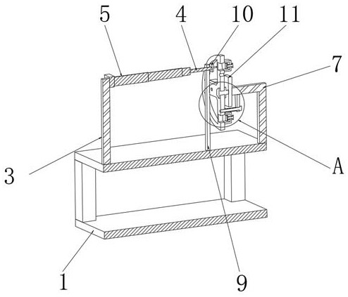
[0020] see Figure 1-3 , a relay detection device capable of improving detection efficiency, comprising a workbench 1, an L-shaped bracket 7 is fixedly installed on one end of the upper surface of the workbench 1, and a mounting plate 11 is fixedly mounted on the top of the L-shaped bracket 7, and the mounting plate 11 is far away from L A rotating shaft 21 is fixedly installed on one side of the type bracket 7, and a periodic feeding assembly is arranged on the outside of the rotating shaft 21. The periodic feeding assembly is used to place the relay and move the relay to the detection position. The upper surface of the workbench 1 is far away from L One end of the type bracket 7 is fixedly installed with a column 3, and the top of the column 3 is fixedly installed with a detection component, which is used for detecting the relay.

[0021] In a specific embodiment of the present invention, through the periodic feeding assembly, the feeding of multiple relays can be completed ...

Embodiment 2

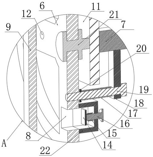
[0023] This embodiment is an improvement made on Embodiment 1. For details, please refer to Figure 1-3 , the periodic feeding assembly includes a turntable 6, the turntable 6 is movably socketed on the outside of the rotating shaft 21, one side of the turntable 6 is provided with a number of through grooves 8, and one side of the turntable 6 is fixed at the corresponding position of each through groove 8 An anti-off cover 22 is installed, and one side of the rotating disk 6 is provided with a locking hole 12 at the corresponding position of each through groove 8. The lower surface of the L-shaped support 7 is provided with a locking mechanism, and the locking mechanism is used to limit the rotating disk 6. Position, several through grooves 8 and several locking holes 12 are all arranged on one side of the turntable 6 around the rotating shaft 21 as the axis.

[0024] In this embodiment: several relays are respectively placed inside the through groove 8, and the turntable 6 ca...

Embodiment 3

[0026] This embodiment is an improvement made on Embodiment 1. For details, please refer to Figure 1-3 , the detection component includes an electric push rod 5, the electric push rod 5 is fixedly installed on the side of the column 3 facing the turntable 6, and the end of the electric push rod 5 away from the column 3 is fixedly installed with a limit column 4, and the limit column 4 is far away from the electric push rod One end of 5 is fixedly installed with connector plate 10, and one side of connector plate 10 is provided with several contact test columns, and the upper surface of workbench 1 is fixedly installed with digital display meter 2, and digital display meter 2 is electrically connected with contact test column.

[0027] In this embodiment: the electric push rod 5 is elongated, so that the electric push rod 5 pushes the limit post 4 and the joint plate 10 to move toward the turntable 6, so that several contact test posts on the joint plate 10 and the relay on the...


PUM


Abstract

The invention relates to the technical field of relay production, and discloses a relay detection device capable of improving detection efficiency. The relay detection device comprises a workbench, wherein an L-shaped support is fixedly mounted at one end of the upper surface of the workbench, a mounting plate is fixedly mounted at the top end of the L-shaped support, a rotating shaft is fixedly mounted on the side, which is away from the L-shaped support, of the mounting plate, and a periodic feeding assembly is movably arranged on the outer side of the rotating shaft. According to the relay detection device capable of improving the detection efficiency, the periodic feeding assembly is arranged, the position of one relay is enabled to correspond to the position of a connector plate by rotating a turntable, the connector plate can detect the relay at the detection position, an operator can rotate the turntable again after detection is completed, and the relay in the next through groove is enabled to be in place, so that the detection time is not delayed when the relay is placed and taken down, the effect of improving the detection efficiency is achieved, and the problem of slow detection speed is avoided.

Description

technical field [0001] The invention relates to the technical field of relay production, in particular to a relay detection device capable of improving detection efficiency. Background technique [0002] The relay is an electrical control device, which is an electrical appliance that makes the controlled quantity undergo a predetermined step change in the electrical output circuit when the change of the input quantity meets the specified requirements. It has a control system and a controlled system. interaction. Usually used in automatic control circuits. [0003] The detection speed of the existing relay detection device is slow. It is necessary to place a relay on the detection station first, and then remove the relay from the detection station after the detection is completed, so that the next relay to be detected can be placed. In the production process, it is necessary to Inspection of many relays, this inspection method will slow down the speed of production. Conte...

Claims


Application Information

Patent Timeline
Patent Type & Authority Applications(China)
IPC IPC(8): B65G29/02B65G47/82G01R31/327
CPCB65G29/02B65G47/82G01R31/327
Inventor 孙超程潜善唐亮胡汉李东风解建刚杜飞关为民李明钱聪
Owner STATE GRID JIANGSU ELECTRIC POWER CO LTD MAINTENANCE BRANCH
Why Eureka
Try Eureka