Hook piece and manufacturing method thereof

A U-shaped, lug-plate technology, applied to building components, cladding/lining, walls, etc., can solve problems such as poor fit of main beams, unstable components, and potential safety hazards

Pending Publication Date: 2022-02-01
吴有喜
View PDF7 Cites 0 Cited by
  • Summary
  • Abstract
  • Description
  • Claims
  • Application Information

AI Technical Summary

Problems solved by technology

[0003] Among the components in the prior art, because their technical processing is affected by welding and other factors, when the

Method used


Image

  • Hook piece and manufacturing method thereof
  • Hook piece and manufacturing method thereof
  • Hook piece and manufacturing method thereof

Examples


Embodiment

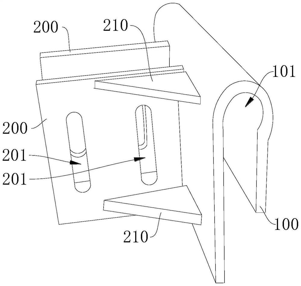
[0048] Please refer to Figure 1-Figure 5 , is shown as an embodiment of the invention.

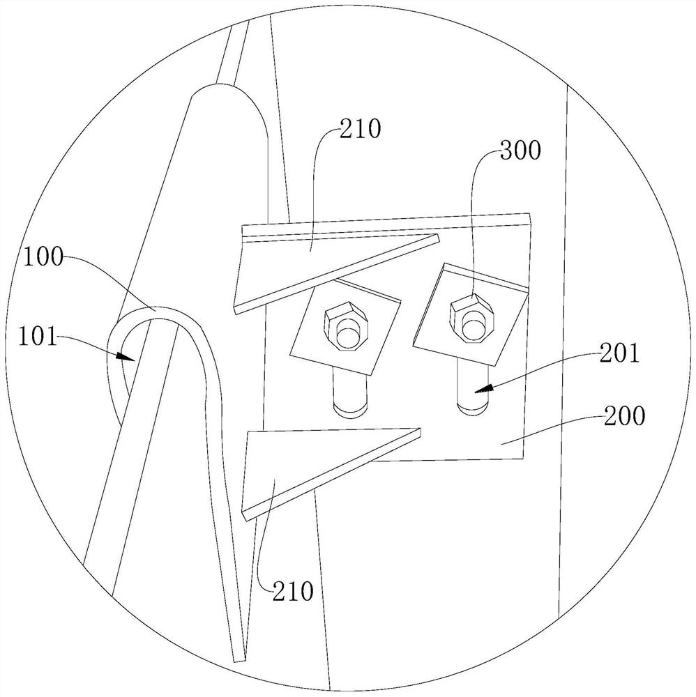
[0049] like figure 1 , 2 As shown, the embodiment of the present application provides a hook piece, which includes a U-shaped piece 100 connected to each other and two lugs 200 , the U-shaped piece 100 has a slot 101 , and the two lugs 200 are arranged alternately.

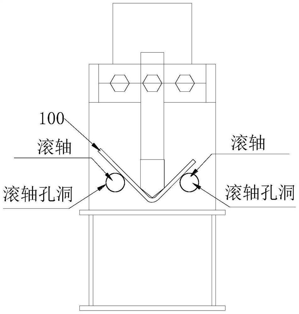
[0050] In this embodiment, the U-shaped piece 100 is fixedly connected to the two ear plates 200 . The U-shaped piece 100 is used for inserting the main beam skewer therein. At this time, the bending part of the U-shaped piece 100 is located on the upper side of the main beam, and the two sides of the U-shaped piece 100 are respectively located on both sides of the main beam. The ear plates 200 are used to be fixed on the main column of the keel, and the two ear plates 200 are respectively located on both sides of the main column of the keel.

[0051] In this embodiment, the embedding groove 101 of the U-shaped member 100 f...


PUM


Abstract

The invention provides a hook piece, and relates to the field of fabricated building components. The hook piece comprises a U-shaped piece and two lug plates which are connected with each other, the U-shaped piece is provided with a caulking groove, and the two lug plates are arranged alternately; the hook piece has better stress effect and stability. In addition, the invention further provides a manufacturing method of the hook piece, multiple procedures are reduced, cost is saved, meanwhile, the component is integrally formed, and the defect that stress is limited by welding quality is overcome.

Description

technical field [0001] The invention relates to the field of assembled building components, in particular to a hook and a manufacturing method thereof. Background technique [0002] The main purpose of the prefabricated building components is: a hook to support the entire exterior decoration. Its advantages are as follows: 1. Prefabricated building components can be standardized and mass-produced, and are not affected by all other uncertain factors such as weather, and the quality is relatively reliable; 2. Environmental protection and energy saving, reducing material waste during construction, and at the same time The generation of construction waste is greatly reduced, and more than 90% of its structural components can be recycled repeatedly, with a high secondary utilization rate; 3. The prefabricated components of the prefabricated building are processed in the factory, which reduces the demand for manpower and construction. Labor intensity of personnel; 4. After the pr...

Claims


Application Information

Patent Timeline
IPC IPC(8): E04B2/96E04F13/22
CPCE04B2/965E04F13/0803
Inventor 吴有喜杨晨辉黄炎明王琳林思敏
Owner 吴有喜
Why Eureka
Try Eureka