
Nano-generator output performance test method based on performance test system

A nanogenerator and testing system technology, applied in the direction of motor generator testing, etc., can solve the problem that the testing of output voltage, current and transfer charge of nanogenerators lacks standardized platform construction and testing process, and cannot reflect the working performance of triboelectric nanogenerators. , delay and signal loss, etc., to achieve a wide range of scientific research and engineering application prospects, standardize the output signal acquisition analysis and performance evaluation, and the effect of long-term acquisition

Pending Publication Date: 2022-02-01
WUHAN UNIV
View PDF0 Cites 0 Cited by
  • Summary
  • Abstract
  • Description
  • Claims
  • Application Information

AI Technical Summary

Problems solved by technology

[0003] Testing and evaluating the output performance of nanogenerators is an important step in characterizing the energy conversion efficiency of devices, but the existing tests for output voltage, current and transferred charges of nanogenerators lack relevant normative platform construction and testing procedures, especially the use of analog There is a large delay and signal loss in the way the acquisition card reads the high-resistance electrometer signal, which leads to large errors or even errors in the measurement results, which cannot reflect the real working performance of the triboelectric nanogenerator constructed

Method used


Image

  • Nano-generator output performance test method based on performance test system
  • Nano-generator output performance test method based on performance test system
  • Nano-generator output performance test method based on performance test system

Examples


Embodiment Construction

[0048] In order to facilitate those of ordinary skill in the art to understand and implement the present invention, the present invention will be described in further detail below in conjunction with the accompanying drawings and embodiments. It should be understood that the implementation examples described here are only used to illustrate and explain the present invention, and are not intended to limit this invention.

[0049] A method for testing the output performance of a nanogenerator based on a performance testing system, the performance testing system comprising: a tubular linear motor, a friction nanogenerator, a high-resistance electrometer, a microprocessor, and a display module;

[0050] The tubular linear motor, friction nanogenerator, high-resistance electrometer, microprocessor, and display module are sequentially connected;

[0051] The triboelectric nanogenerator includes: PTFE film and conductive copper film;

[0052] The conductive copper film is evenly adh...


PUM


Abstract

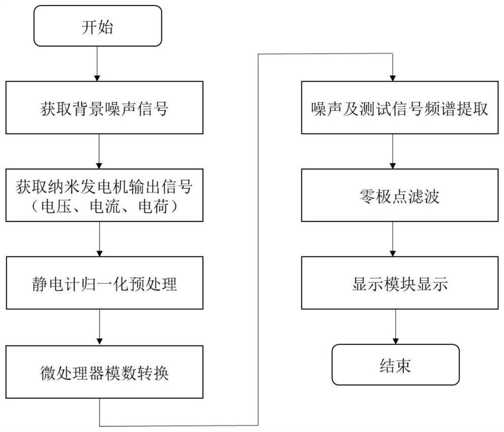
The invention provides a nanometer generator output performance test method based on a performance test system. The performance test system comprises a tubular linear motor, a friction nanometer generator, a high-resistance electrometer, a microprocessor and a display module. According to the nanogenerator output performance test method, a high-resistance electrometer is matched with a microprocessor to realize synchronous analog-digital signal conversion of current, voltage or charge analog signals to be tested; and meanwhile, a high-speed digital signal acquisition unit arranged in the microprocessor is used for quickly collecting output digital signals in a lossless manner. In this way, noise characteristic frequencies are screened out by combining spectrum characteristics of background noise and test data, and a filter is constructed on the basis of the noise characteristic frequencies to carry out post-processing on the collected signals, so that high-frequency and background noise interference is filtered out. According to the method, lossless and accurate measurement of the output signal of the friction nanometer generator is realized.

Description

technical field [0001] The invention belongs to the technical field of generators, in particular to a method for testing the output performance of a nanometer generator based on a performance testing system. Background technique [0002] Nanogenerators, including triboelectric nanogenerators and piezoelectric nanogenerators, have broad application prospects in the field of micro-energy collection and conversion, such as wearable self-powered electronic devices based on nanogenerators, blue energy collection, wind energy and water droplet energy. collection etc. [0003] Testing and evaluating the output performance of nanogenerators is an important step in characterizing the energy conversion efficiency of devices, but the existing tests for output voltage, current and transferred charges of nanogenerators lack relevant normative platform construction and testing procedures, especially the use of analog There is a large time delay and signal loss in the way the acquisition ...

Claims


Application Information

Patent Timeline
IPC IPC(8): G01R31/34
CPCG01R31/34
Inventor 李祎吴豪颖肖淞唐炬张晓星潘成曾福平
Owner WUHAN UNIV
Learn More