Full-automatic platform gauge measuring method based on laser radar

A technology of laser radar and measurement method, which is applied to measurement devices, radio wave measurement systems, and re-radiation of electromagnetic waves, etc., can solve problems such as unfavorable unification, automated surveys, ordinary cameras have no depth information, and measurement time is limited, etc. Achieve the effect of improving the overall measurement accuracy, wide scanning coverage, and improving segmentation accuracy

Pending Publication Date: 2022-02-01
杭州中科睿鉴科技有限公司 +1
View PDF0 Cites 0 Cited by
  • Summary
  • Abstract
  • Description
  • Claims
  • Application Information

AI Technical Summary

Problems solved by technology

[0003] The existing domestic and foreign research methods on the measurement of high-speed rail platform boundaries can be divided into infrared, sound wave, camera, radar, etc. from the types of sensors. The ranging method based on infrared sensors and ultrasonic sensors has high accuracy, but the The information is relatively limited, and most of them adopt the form of slide rail movement, which requires additional manpower to assist. During the skylight period, the laser measuring trolley is used to measure the distance between the middle of the rail track and the edge of the platform at certain fixed points. The measurement process of this method is complicated. The operation process is cumbersome and the measurement time is limited, which is not conducive to unified and automated surveying; based on the limit range measurement of industrial camera vision, most scenes are fixed equipment, which reduces the accuracy loss caused by movement to a certain extent, but the camera The image quality is greatly affected by weather, light, and environment, which directly affects the subsequent image processing, and ordinary cameras have no depth information, and the measurement accuracy cannot be guaranteed

Method used


Image

  • Full-automatic platform gauge measuring method based on laser radar
  • Full-automatic platform gauge measuring method based on laser radar
  • Full-automatic platform gauge measuring method based on laser radar

Examples


Embodiment Construction

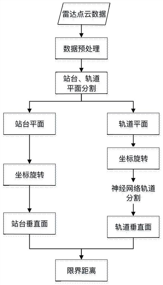
[0060] This embodiment is a fully automatic platform boundary measurement method based on laser radar, which specifically includes the following steps:

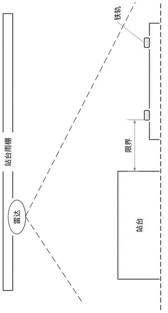
[0061] S1. Obtain the point cloud data of the station and track area; scan the station and track area with laser through the laser radar installed on the top of the platform, obtain point cloud data through calculation, and filter the 3D point cloud data to remove noise .

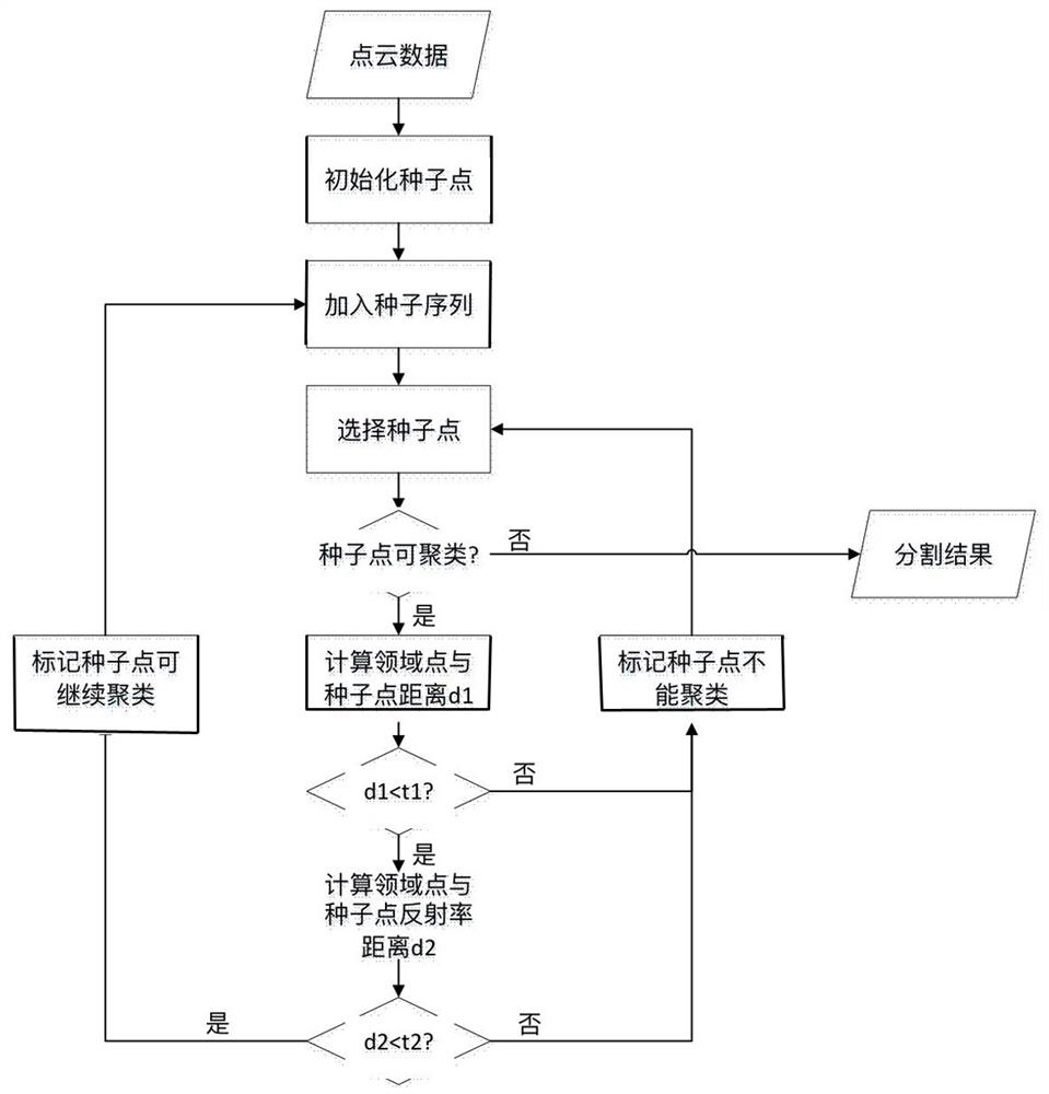
[0062] S2. Using a traditional segmentation algorithm based on region growing, segment the platform plane and the track plane. Since the reflectivity of the platform and the track plane are different, the reflectivity information is added to the region growing segmentation, and the specific steps are as follows:

[0063] (1) Obtain point cloud data, initialize seed points, and add them to the seed sequence

[0064] (2) Select the seed points marked as clusterable, and if the seed points are marked as non-clusterable, exit the process and obtain the segme...


PUM


Abstract

The invention relates to a full-automatic platform gauge measuring method based on a laser radar. According to the technical scheme, the method comprises the steps of obtaining the point cloud data of a station and a rail area; segmenting a platform plane and a rail plane from the point cloud data by using a segmentation algorithm based on region growth, and adding reflectivity information in region growth segmentation; transforming a data point set of the platform plane and the rail plane into a plane parallel to a coordinate axis through coordinate transformation; according to the position of a platform and the priori knowledge related to the rail distance, drawing a rail region of interest on the rail plane, utilizing a neural network pointnet + + to complete rail segmentation, wherein the input of the pointnet + + is 4-dimensional and 3-dimensional coordinates + 1-dimensional reflectivity; and carrying out plane fitting on the rail plane and the platform plane, calculating the vertical plane of the rail edge and the vertical plane of the platform edge, calculating the distance between the vertical planes of the rail and the platform, and completing the gauge measurement. The method is suitable for the field of radar point cloud distance measurement.

Description

technical field [0001] The invention relates to a laser radar-based fully automatic platform limit measurement method. Applicable to the field of radar point cloud ranging. Background technique [0002] With the continuous improvement of the high-speed rail system, the number of high-speed rail stations is also increasing rapidly. The boundary between the railway platform and the rails is an important guarantee to ensure the safety of railway operation, especially the high-speed rail platform. The distance from the edge of the platform when the high-speed rail stops is an important measurement Different models have different distance values, and the centimeter-level or even millimeter-level deformation of the rails or platforms will have an important impact on the safe docking of trains. Therefore, the monitoring and management of station area platform boundaries has become one of the key tasks of railway safety work one. [0003] The existing domestic and foreign research...

Claims


Application Information

Patent Timeline
IPC IPC(8): G01S17/08G01S17/931
CPCG01S17/08G01S17/931
Inventor 曹娟武琦龚健吕永标谢添
Owner 杭州中科睿鉴科技有限公司
Why Eureka
Try Eureka