
Fire sprinkler with alarm function

A sprinkler and fire-fighting technology, applied in electrical fire alarms, electrical transmission signal systems, fire rescue and other directions, can solve the problems of troublesome installation, delayed fire positioning time, delayed fire fighting, etc., and achieves simple structure, reasonable design and maintenance. handy effect

Pending Publication Date: 2022-02-08
刘锐杰
View PDF7 Cites 0 Cited by
  • Summary
  • Abstract
  • Description
  • Claims
  • Application Information

AI Technical Summary

Problems solved by technology

[0002] The alarm function of the traditional fire sprinkler is completed by the water flow alarm or water flow indicator in the fire pipeline. The cost of the water flow alarm and water flow indicator is relatively high, and the water flow alarm or water flow indicator needs to be installed at the main pipe position. This is more troublesome to install. Install the water flow alarm or water flow indicator to the main pipe, so that it is not clear which sprinkler in the fire protection system is operating when in use, resulting in delays in fire location.
In addition, in some places now, due to historical or cost reasons, fire sprinklers are not installed on independent fire pipelines, but on domestic water pipelines. It is impossible to install traditional water flow alarms or water flow indicators on domestic water pipelines. device, so that when there is a fire hazard, there is no alarm action at all when the fire sprinkler operates, causing delay in fire fighting; in addition, because water spray will cause certain property damage, and generally if there is no manual valve closing, water spray will always Continuous, without alarm action, there is no way to control the loss of sprinkler

Method used


Image

  • Fire sprinkler with alarm function
  • Fire sprinkler with alarm function
  • Fire sprinkler with alarm function

Examples


Embodiment Construction

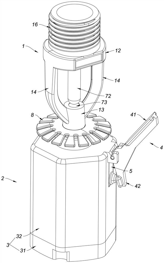
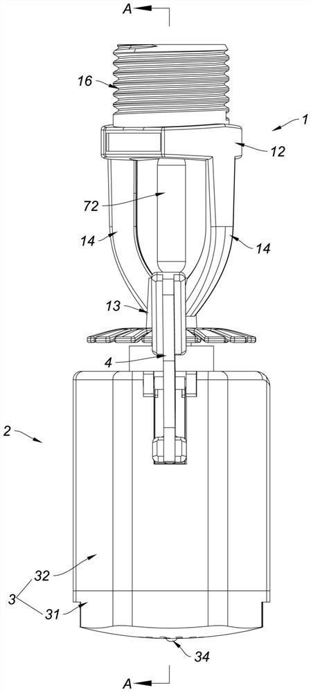
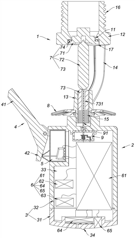
[0020] Such as figure 1 , figure 2 , image 3 As shown, a fire sprinkler with an alarm function in this embodiment includes a sprinkler body 1 and an alarm 2, the sprinkler body 1 is provided with a water outlet 11, and a water outlet 11 is installed on the sprinkler body 1 to seal the water outlet 11. Blocked sensing valve body 7; the alarm 2 includes a casing 3, a water retaining lever 4, an alarm switch 5 and an alarm circuit 6; the casing 3 includes a lower cover 31 and an upper casing 32, and the upper casing 32 is connected to The bottom of the nozzle body 1; the lower cover 31 is connected with the upper shell 32 to form a cavity 33, the lower cover 31 and the upper shell 32 are fixed together by screws, and the bottom surface of the lower cover 31 is an arc-shaped convex surface. A circular protrusion 34 is formed in the center of the bottom surface of the cover 31; the water retaining lever 4 is provided with a water retaining end 41 and a pressing end 42, the wate...


PUM


Abstract

The invention relates to a fire sprinkler with an alarm function, which comprises a sprinkler body and an alarm, the sprinkler body is provided with a water outlet, and the sprinkler body is provided with an induction valve body for blocking the water outlet. The alarm comprises a shell, a water retaining deflector rod, an alarm switch and an alarm circuit; wherein the shell comprises a lower cover and an upper shell, and the upper shell is connected to the bottom of the nozzle body; the lower cover and the upper shell are connected to form a cavity, the bottom surface of the lower cover is an arc-shaped convex surface, and a circular bulge is formed in the center of the bottom surface of the lower cover; a water retaining end and a pressing end are arranged on the water retaining deflector rod, the water retaining end is arranged close to the water outlet, and the water retaining deflector rod is rotatably mounted on the shell. The alarm circuit is arranged in the cavity of the shell; the alarm switch is installed on the shell and used for controlling starting of the alarm circuit, and the action triggering end of the alarm switch makes contact with the pressing end. The fire sprinkler has the advantages of being convenient to construct, maintain and use, capable of easily improving an existing fire sprinkler and the like.

Description

technical field [0001] The invention relates to the technical field of fire-fighting equipment, in particular to a fire-fighting nozzle with an alarm function. Background technique [0002] The alarm function of the traditional fire sprinkler is completed by the water flow alarm or water flow indicator in the fire pipeline. The cost of the water flow alarm and water flow indicator is relatively high, and the water flow alarm or water flow indicator needs to be installed at the main pipe position. It is cumbersome to install like this, and the water flow alarm or the water flow indicator is installed at the main pipe position, so that it is not clear which sprinkler in the fire protection system is operating when in use, so that the time delay of fire location is caused. In addition, in some places now, due to historical or cost reasons, fire sprinklers are not installed on independent fire pipelines, but on domestic water pipelines. It is impossible to install traditional wa...

Claims


Application Information

Patent Timeline
IPC IPC(8): A62C31/00A62C31/28A62C37/11G08B7/06G08B17/06
CPCA62C31/005A62C31/28A62C37/11G08B17/06G08B7/06
Inventor 曹乐凡刘锐杰
Owner 刘锐杰
Learn More