
Separating and cleaning system for oil mist purifier

A cleaning system and oil mist separation technology, applied in the field of separation and cleaning systems, can solve problems such as general collection effect, failure to work normally, and inability to fully respond, so as to improve the treatment effect, improve the service life and working hours, and ensure the oil mist separation speed Effect

Pending Publication Date: 2022-02-08
喻梅
View PDF10 Cites 0 Cited by
  • Summary
  • Abstract
  • Description
  • Claims
  • Application Information

AI Technical Summary

Problems solved by technology

[0002] As we all know, the oil mist purifier is a professional equipment that collects and evolves environmental pollutants such as oil mist, water mist, and dust generated in mechanical processing. The oil mist particles collide under the action of the wind wheel in the oil mist purifier, and the tiny particles aggregate into larger particles that can be controlled, and are collected and recycled through the return port. The collection effect is general, while The vibration of the oil mist purification equipment using chemical properties will not work normally during operation, and it needs to be under the condition of anti-leakage to ensure that the oil pollution purification can be completed normally. Distribute ions outward, so that the passing oil mist is carried by different electrodes to achieve the effect of water-oil separation. The treatment effect of oil-liquid separation is better but cannot fully react

Method used


Image

  • Separating and cleaning system for oil mist purifier
  • Separating and cleaning system for oil mist purifier
  • Separating and cleaning system for oil mist purifier

Examples


Embodiment Construction

[0024] The following are specific embodiments of the present invention and in conjunction with the accompanying drawings, the technical solutions of the present invention are further described, but the present invention is not limited to these embodiments.

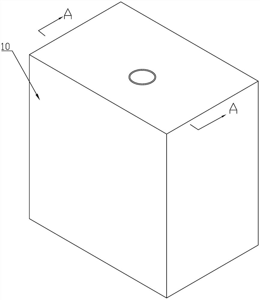
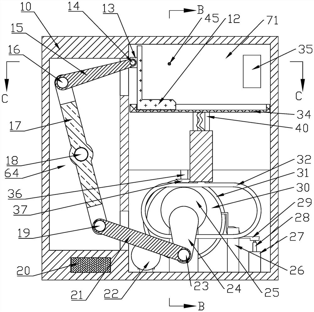
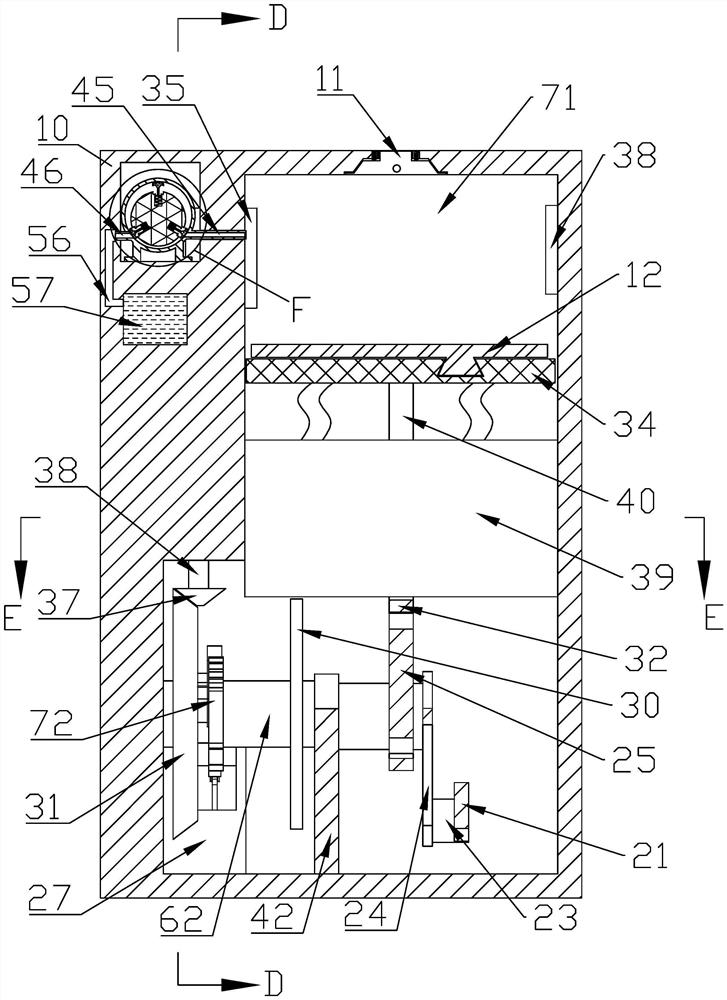
[0025] Such as figure 1As shown, a separation and cleaning system for an oil mist purifier includes a housing 10, which is characterized in that the housing 10 is provided with a left chamber 64, and the left chamber 64 is fixed with a fixing rod 18. 10 is provided with a circular groove 48 on the left side, an electric box 20 is provided on the lower left side of the housing 10, an air inlet and outlet valve 11 is provided on the upper side wall of the housing 10, a cleaning agent box 57 is provided on the upper left side of the housing 10, and a cleaning agent box 57 is provided on the upper left side of the housing 10. The left side of 10 is provided with U-shaped pipe 56, and U-shaped pipe 56 is connected with cleaning...


PUM


Abstract

The invention belongs to the field of oil mist purification, and relates to a separating and cleaning system for an oil mist purifier. The separating and cleaning system comprises a shell, and is characterized in that a left side cavity is formed in the shell, a fixing rod is fixedly arranged in the left side cavity, a circular groove is formed in the left side of the shell, an electric box is arranged at the lower left part of the shell, an air inlet and outlet valve is arranged on the upper side wall of the shell, a cleaning agent box is arranged on the upper left portion of the shell, a U-shaped pipe is arranged on the left side of the shell, and the U-shaped pipe is connected with the cleaning agent box. When oil mist in air generated in the industry is treated, the oil mist is sucked and discharged by moving the oil mist to enable the air pressure in the cavity to change, oil and water are separated in an electrode deposition mode, and when more oil stains are deposited, cleaning liquid is sprayed at regular time to clean the oil stains on an oil side electrode, and finally the oil stains are discharged.

Description

technical field [0001] The invention belongs to the field of oil mist purification, and in particular relates to a separation and cleaning system for an oil mist purifier. Background technique [0002] As we all know, the oil mist purifier is a professional equipment that collects and evolves environmental pollutants such as oil mist, water mist, and dust generated in mechanical processing. The oil mist particles collide under the action of the wind wheel in the oil mist purifier, and the tiny particles aggregate into larger particles that can be controlled, and are collected and recycled through the return port. The collection effect is general, while The vibration of the oil mist purification equipment using chemical properties will not work normally during operation, and it needs to be under the condition of air leakage prevention to ensure that the oil pollution purification can be completed normally. There are many restrictions. The other method is electrode deposition....

Claims


Application Information

Patent Timeline
Patent Type & Authority Applications(China)
IPC IPC(8): B03C3/45B03C3/78B03C3/34
CPCB03C3/45B03C3/78B03C3/34
Inventor 喻梅
Owner 喻梅
Learn More