Single-punch multi-die sheet metal part stamping machining automatic line

A technology of stamping processing and sheet metal parts, which is applied in the field of sheet metal stamping, can solve the problems of lack of reinforcement mechanism of sheet metal parts, low quality of stamping parts, increase of production cost, etc., so as to improve the quality of output, improve efficiency and save The effect of production costs

Pending Publication Date: 2022-02-08
夏俊豪
View PDF1 Cites 2 Cited by
  • Summary
  • Abstract
  • Description
  • Claims
  • Application Information

AI Technical Summary

Problems solved by technology

[0005] 1. When the equipment stamps sheet metal parts, it lacks a reinforcement mechanism for sheet metal parts, which makes the quality of stamping parts not high
[0006] 2. The equipment needs to add lubricant during stamping. On the one hand, it can dissipate heat, and on the other hand, it can prevent the workpiece from sticking to the pressed part. This requires adding additional driving parts such as pumps to the equipment, which increases the production cost.
[0007] 3. After the stamping of the workpiece is completed, the surface temperature will be relatively high. It is necessary to wait for the workpiece to cool down before being recycled by the workers, which leads to low production efficiency.

Method used


Image

  • Single-punch multi-die sheet metal part stamping machining automatic line
  • Single-punch multi-die sheet metal part stamping machining automatic line
  • Single-punch multi-die sheet metal part stamping machining automatic line

Examples


Embodiment Construction

[0036]The following will clearly and completely describe the technical solutions in the embodiments of the present invention with reference to the accompanying drawings in the embodiments of the present invention. Obviously, the described embodiments are only some, not all, embodiments of the present invention. Based on the embodiments of the present invention, all other embodiments obtained by persons of ordinary skill in the art without making creative efforts belong to the protection scope of the present invention.

[0037] In describing the present invention, it is to be understood that the terms "center", "longitudinal", "transverse", "length", "width", "thickness", "upper", "lower", "front", " Back", "Left", "Right", "Straight", "Horizontal", "Top", "Bottom", "Inner", "Outer", "Clockwise", "Counterclockwise", etc. or The positional relationship is based on the orientation or positional relationship shown in the drawings, which is only for the convenience of describing th...


PUM


Abstract

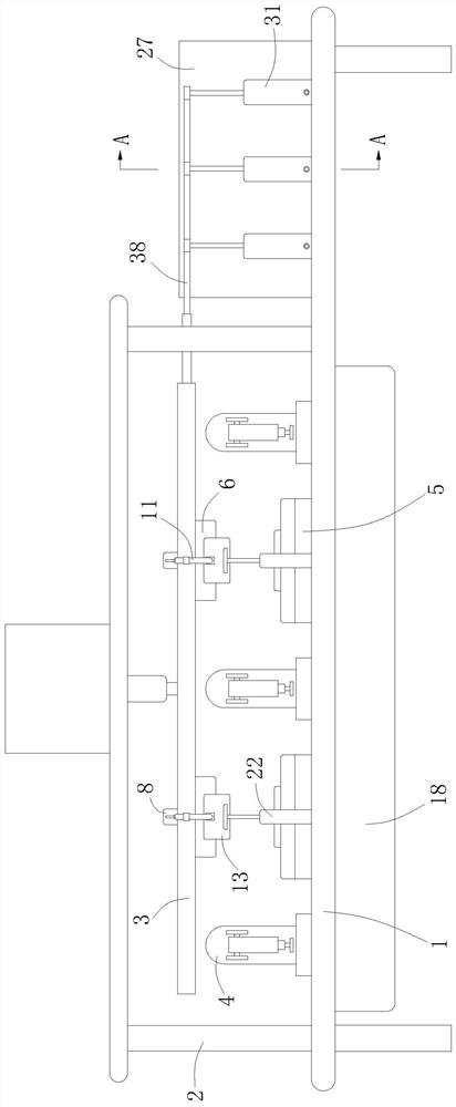
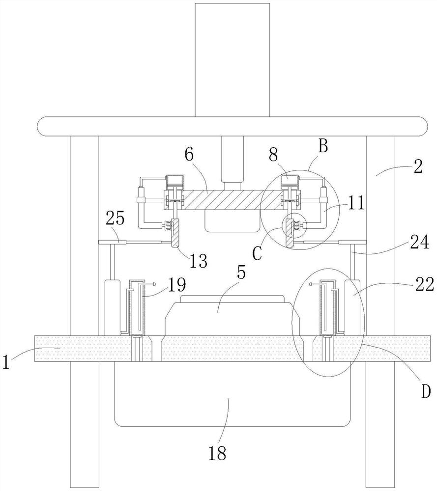
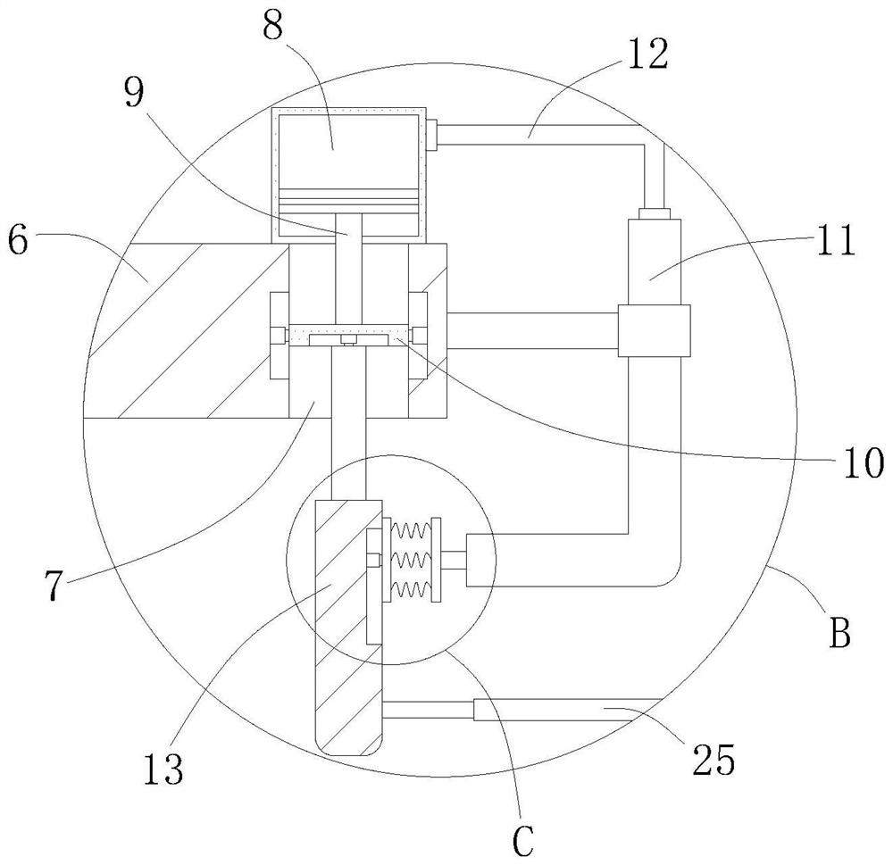
The invention relates to the technical field of sheet metal stamping, in particular to a single-punch multi-die sheet metal part stamping machining automation line which comprises a workbench, a mounting frame, a lifting frame, a mechanical arm, an objective table and a pressing part; a first piston cylinder is fixedly arranged at the upper end of each mounting hole, and an automatic clamping mechanism is arranged between each first piston cylinder and a clamping plate; an automatic lubricating mechanism acting on the storage tank is arranged between a third piston cylinder and the clamping plate; and an air drying and cooling mechanism is arranged on the top plate. The air pressure in the first piston cylinder is changed through the descending action of the lifting frame, the two clamping plates are driven to get close to each other, and then the machining precision is improved; under the condition that no extra driving part exists, the lubricating procedure is completed, so that the production cost is saved, and the production quality is improved; and the lifting frame moves up and down to drive the fourth piston rod to move, so that air in the fourth piston cylinder and the fifth piston cylinder is used for blowing, air drying and cooling of workpieces are achieved, and the production efficiency is improved.

Description

technical field [0001] The invention relates to the technical field of sheet metal stamping, in particular to an automatic line for stamping processing of single punch and multi-die sheet metal parts. Background technique [0002] Stamping is a forming processing method that relies on presses and molds to apply external forces to plates, strips, pipes, and profiles to cause plastic deformation or separation, thereby obtaining workpieces of required shape and size. Compared with castings and forgings, stamping parts have the characteristics of thinness, uniformity, lightness and strength. Stamping can produce workpieces with ribs, ribs, undulations or flanges that are difficult to manufacture by other methods to increase their rigidity. [0003] The existing patent (notification number: CN110328272A) is an automatic line for stamping processing of single-punch and multi-die sheet metal parts, including a body, a transmission mechanism, a support mechanism, a collection mecha...

Claims


Application Information

Patent Timeline
Patent Type & Authority Applications(China)
IPC IPC(8): B21D43/00B21D37/18B21D37/16F26B21/00
CPCB21D43/003B21D37/18B21D37/16F26B21/001F26B21/004
Inventor 夏俊豪孙家正
Owner 夏俊豪
Why Eureka
Try Eureka