Sewage pump

A technology of sewage pump and sewage outlet, applied in the direction of pump, pump element, non-variable-capacity pump, etc., can solve the problems of reducing drainage efficiency, poor shock absorption of sewage pump, pipeline blockage, etc., so as to improve drainage efficiency and avoid pipeline blockage. , easy to adjust effect

Pending Publication Date: 2022-02-08
YANGZHOU HONGYUE MECHANICAL CO LTD
View PDF1 Cites 0 Cited by
  • Summary
  • Abstract
  • Description
  • Claims
  • Application Information

AI Technical Summary

Problems solved by technology

[0004] The purpose of the present invention is to provide a sewage pump to solve the problem that the connection between the sewage outlet and the pipeline of the sewage pump proposed in the above background technology is unstable, the installation and fixation have

Method used


Image

  • Sewage pump
  • Sewage pump
  • Sewage pump

Examples


Example Embodiment

[0022] Embodiment one:

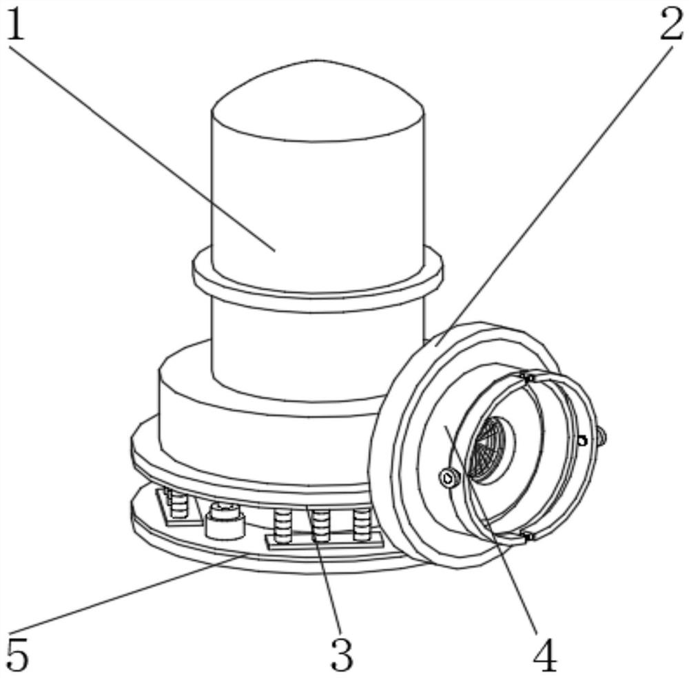
[0023] see Figure 1-5 , the present invention provides a technical solution: a sewage pump, comprising a pump body 1, the outer wall of the pump body 1 is fixedly connected with a sewage outlet 2, the outer surface of the lower end of the pump body 1 is fixedly connected with a chassis 3, and one end of the sewage outlet 2 is A filter fixing mechanism 4 is fixedly connected to the surface, and a shock absorbing mechanism 5 is fixedly connected to the outer surface of one end of the chassis 3 .

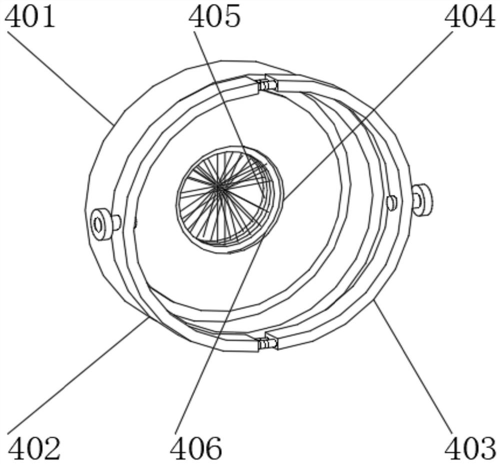
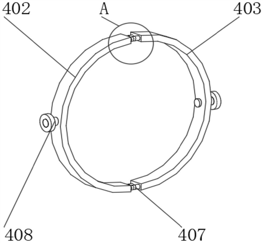
[0024] In this embodiment, by installing and fixing the pipe connecting ring 401 on the sewage outlet 2, when the sewage is discharged, the pipe is inserted into the pipe connecting ring 401, and the pipe mouth is aligned with the connecting port 404, and then the first arc ring 402 Fix the No. 2 arc-shaped ring 403 at the joint between the pipe and the pipe connecting ring 401, tighten the fixing assembly 408, the pipe can be fixed, and the No. 1 spring 407 ...

Example Embodiment

[0031] Embodiment two:

[0032] Specifically, the damping mechanism 5 includes a No. 1 rubber ring 501, a No. 2 rubber ring 502, a mounting plate 503, a No. 2 spring 504, and a hydraulic column 505. The mounting plate 503 is located at one end of the No. 1 rubber ring 501 and the No. 2 rubber ring 502. , the second spring 504 is located on the outer surface of one end of the mounting plate 503 , and the hydraulic column 505 is located between the first rubber ring 501 and the second rubber ring 502 .

[0033] In this embodiment, the shock-absorbing mechanism 5 is beneficial to the shock-absorbing of the sewage pump and avoids its strong shaking.

[0034] Specifically, the mounting plate 503 is installed on one end of the No. 1 rubber ring 501 and the No. 2 rubber ring 502 through a set screw, and the outer surface of one end of the mounting plate 503 is welded to the outer surface of one end of the No. 2 spring 504. The number of springs 504 is several groups.

[0035] In th...


PUM


Abstract

The invention discloses a sewage pump in the field of sewage pumps, which comprises a pump body, the outer wall of the pump body is fixedly connected with a sewage outlet, the outer surface of the lower end of the pump body is fixedly connected with a chassis, the outer surface of one end of the sewage outlet is fixedly connected with a filtering fixing mechanism, and the outer surface of one end of the chassis is fixedly connected with a damping mechanism. The filtering fixing mechanism comprises a pipeline connecting ring, a first arc-shaped ring, a second arc-shaped ring, a connecting opening, a first filter screen, a second filter screen, a first spring and a fixing assembly, wherein the first arc-shaped ring and the second arc-shaped ring are located on the outer wall of the pipeline connecting ring, and the connecting opening is located in the middle of the pipeline connecting ring; the first filter screen and the second filter screen are located on the inner wall of the connecting opening. The pipeline is stably connected with the sewage outlet, installation and fixation are not limited, and impurities in sewage can be filtered, so that the pipeline is prevented from being blocked, and the drainage efficiency is improved; according to the arrangement, the damping performance is good, large noise cannot be generated, and shaking is not prone to occurring.

Description

technical field [0001] The invention belongs to the field of sewage pumps, in particular to a sewage pump. Background technique [0002] The sewage pump is a kind of pump product in which the pump and the motor are integrated and submerged into the liquid at the same time. Compared with the general horizontal pump or vertical sewage pump, the sewage pump has a compact structure and a small footprint. It is convenient to install and maintain. Large-scale sewage pumps are generally equipped with automatic coupling devices for automatic installation. Installation and maintenance are quite convenient. However, a sewage pump that appears on the market still has various deficiencies and cannot meet the production requirements. need. [0003] According to the patent application number CN202021187256.5, there are still some defects in a sewage pump. The connection between the sewage outlet and the pipeline in the sewage pump is not stable. Blockage reduces the drainage efficiency....

Claims


Application Information

Patent Timeline
IPC IPC(8): F04D29/70F04D29/66F04D29/60
CPCF04D29/708F04D29/669F04D29/605
Inventor 邰军虎
Owner YANGZHOU HONGYUE MECHANICAL CO LTD
Why Eureka
Try Eureka