Residential kitchen and bath exhaust system control device and method

A control device, kitchen and bathroom technology, applied in the field of kitchen and bathroom exhaust, can solve problems such as poor smoke exhaust

Active Publication Date: 2022-02-08
HANGZHOU ROBAM APPLIANCES CO LTD
View PDF13 Cites 2 Cited by
  • Summary
  • Abstract
  • Description
  • Claims
  • Application Information

AI Technical Summary

Problems solved by technology

At present, the kitchen and bathroom are independently exhausted. During the peak period of use, there is a common problem of poor smoke exhaust in the middle and lower floors.

Method used


Image

  • Residential kitchen and bath exhaust system control device and method
  • Residential kitchen and bath exhaust system control device and method
  • Residential kitchen and bath exhaust system control device and method

Examples


Embodiment 1

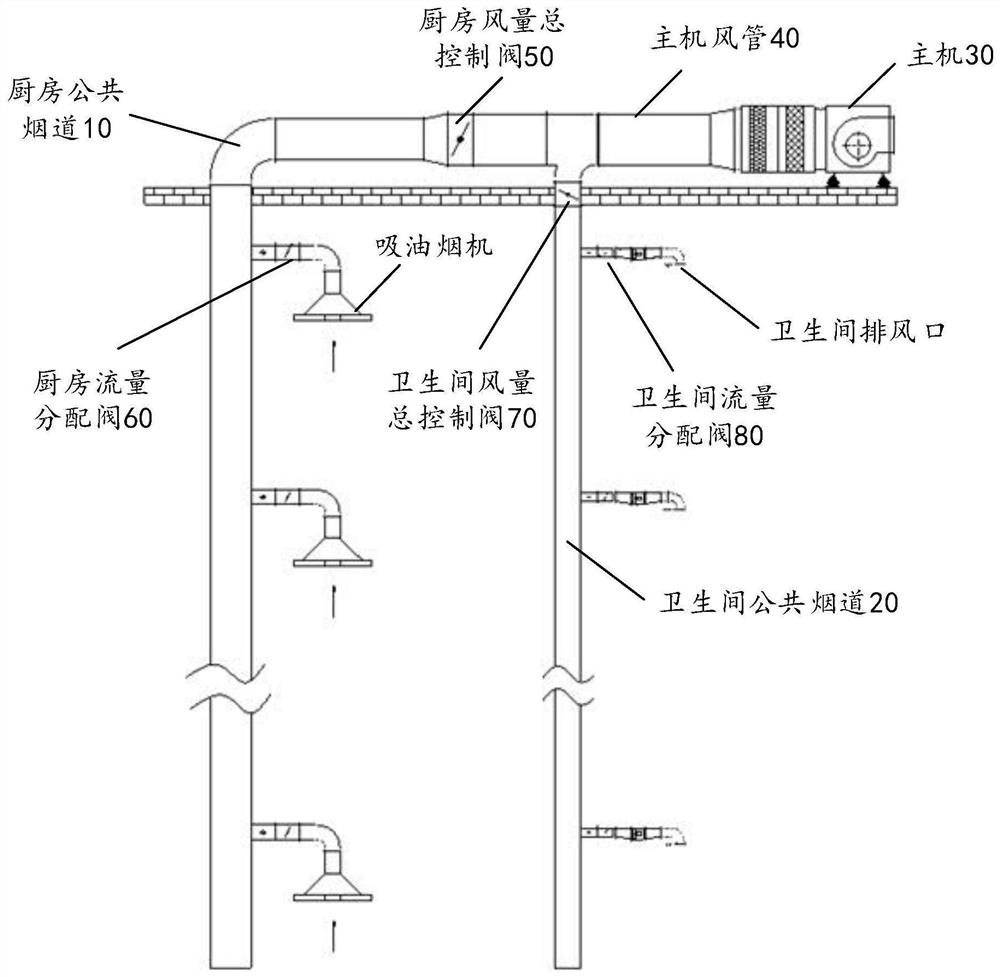
[0023] figure 1 It is a schematic diagram of a control device for a residential kitchen and bathroom exhaust system provided according to an embodiment of the present invention. Such as figure 1 As shown, the device includes: kitchen public flue 10, bathroom public flue 20, host 30 and host air duct 40; the device also includes: kitchen air volume master control valve 50, kitchen flow distribution valve 60, bathroom air volume master control valve 70 and toilet flow distribution valve 80. Wherein, the host 30 is connected to the first end of the host air duct 40 ;

[0024] Specifically, the kitchen air volume master control valve 50 is arranged at the interface between the kitchen common flue 10 and the host air duct 40 for controlling the total exhaust air volume of the kitchen common flue 10 .

[0025] The kitchen flow distribution valve 60 is arranged at the end of the range hood air duct of each kitchen near the interface of the common kitchen flue 10, and is used to co...

Embodiment 2

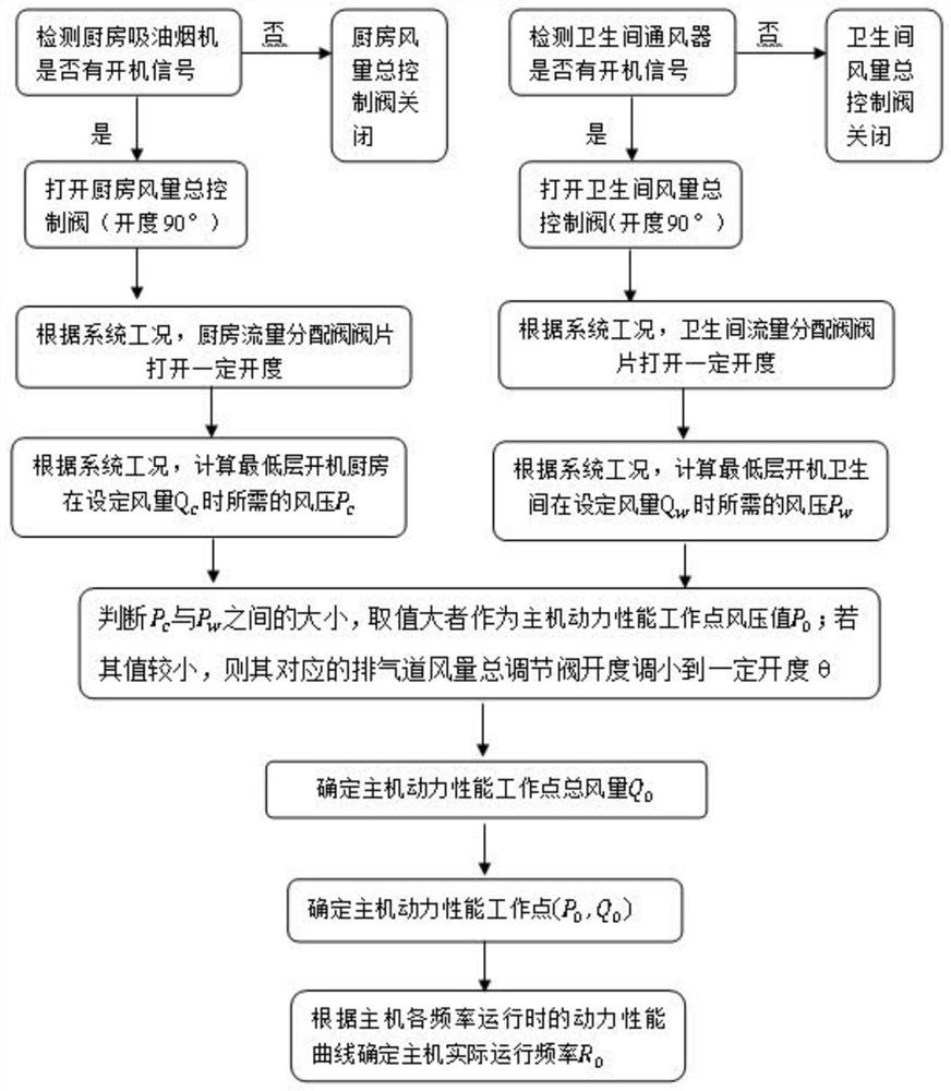
[0057] Figure 5 It is a flow chart of another control method for a residential kitchen and bathroom exhaust system provided according to an embodiment of the present invention. The method is applied to a residential kitchen and bathroom exhaust system control device; the residential kitchen and bathroom exhaust system control device includes: kitchen public flue , bathroom public flue, host, host air duct, kitchen air volume master control valve, kitchen flow distribution valve, bathroom air volume master control valve and toilet flow distribution valve; wherein, the host is connected to the first end of the host air duct; kitchen public smoke Both the public flue and the bathroom flue are connected to the second end of the main machine air duct. Such as Figure 5 As shown, the method specifically includes the following steps:

[0058] Step S402, based on the operating parameters of the control device of the residential kitchen and bathroom exhaust system, determine the tar...


PUM


Abstract

The invention provides a residential kitchen and bath exhaust system control device and method. The device comprises a kitchen public flue, a toilet public flue, a host and a host air pipe, and also comprises a kitchen air volume main control valve, a kitchen flow distribution valve, a toilet air volume main control valve and a toilet flow distribution valve, wherein the kitchen air volume main control valve is used for controlling the exhaust air volume of the kitchen public flue; the kitchen flow distribution valve is used for controlling the exhaust air rate of a range hood air pipe of each kitchen; the toilet air volume main control valve is used for controlling the exhaust air volume of the public flue of the toilet; the toilet flow distribution valve is used for controlling the exhaust air rate of a ventilator air pipe of each toilet; and the host is used for determining a target operation frequency based on the working parameters of the residential kitchen and bath exhaust system control device and providing power for the residential kitchen and bath exhaust system control device at the target operation frequency. The technical problem that a kitchen and a toilet exhaust air independently, and in the use peak period, smoke exhaust of middle and lower floors is unsmooth in the prior art is solved.

Description

technical field [0001] The invention relates to the technical field of kitchen and bathroom exhaust, in particular to a control device and method for a residential kitchen and bathroom exhaust system. Background technique [0002] In existing residential buildings, kitchen oil fumes are discharged from the roof through the kitchen public exhaust duct, while bathroom ventilation is discharged from the roof through the bathroom public flue. The two exhaust methods are independent of each other. Kitchen exhaust can be exhausted through range hoods or centralized smoke exhaust, bathroom exhaust can be natural ventilation, toilet ventilator or centralized mechanical exhaust. At present, the kitchen and bathroom are independently exhausted. During the peak period of use, there is generally a problem of poor smoke exhaust in the middle and lower floors. Contents of the invention [0003] In view of this, the object of the present invention is to provide a control device and meth...

Claims


Application Information

Patent Timeline
Patent Type & Authority Applications(China)
IPC IPC(8): F24C15/20E04F17/02E04F17/04E03D9/04
CPCF24C15/20F24C15/2021E04F17/02E04F17/04E03D9/04
Inventor 任富佳李富强李明费本开陈晓伟
Owner HANGZHOU ROBAM APPLIANCES CO LTD
Why Eureka
Try Eureka