
Self-capacitance touch panel

A touch panel, self-capacitance technology, applied in the direction of instruments, electrical digital data processing, data processing input/output process, etc., can solve the problem of inaccurate touch monitoring of touch electrodes 10 and the second row of touch electrodes 10 Inaccurate touch performance, inaccurate touch monitoring of touch electrodes, etc.

Pending Publication Date: 2022-02-08
WUHAN CHINA STAR OPTOELECTRONICS TECH CO LTD +1
View PDF5 Cites 0 Cited by
  • Summary
  • Abstract
  • Description
  • Claims
  • Application Information

AI Technical Summary

Problems solved by technology

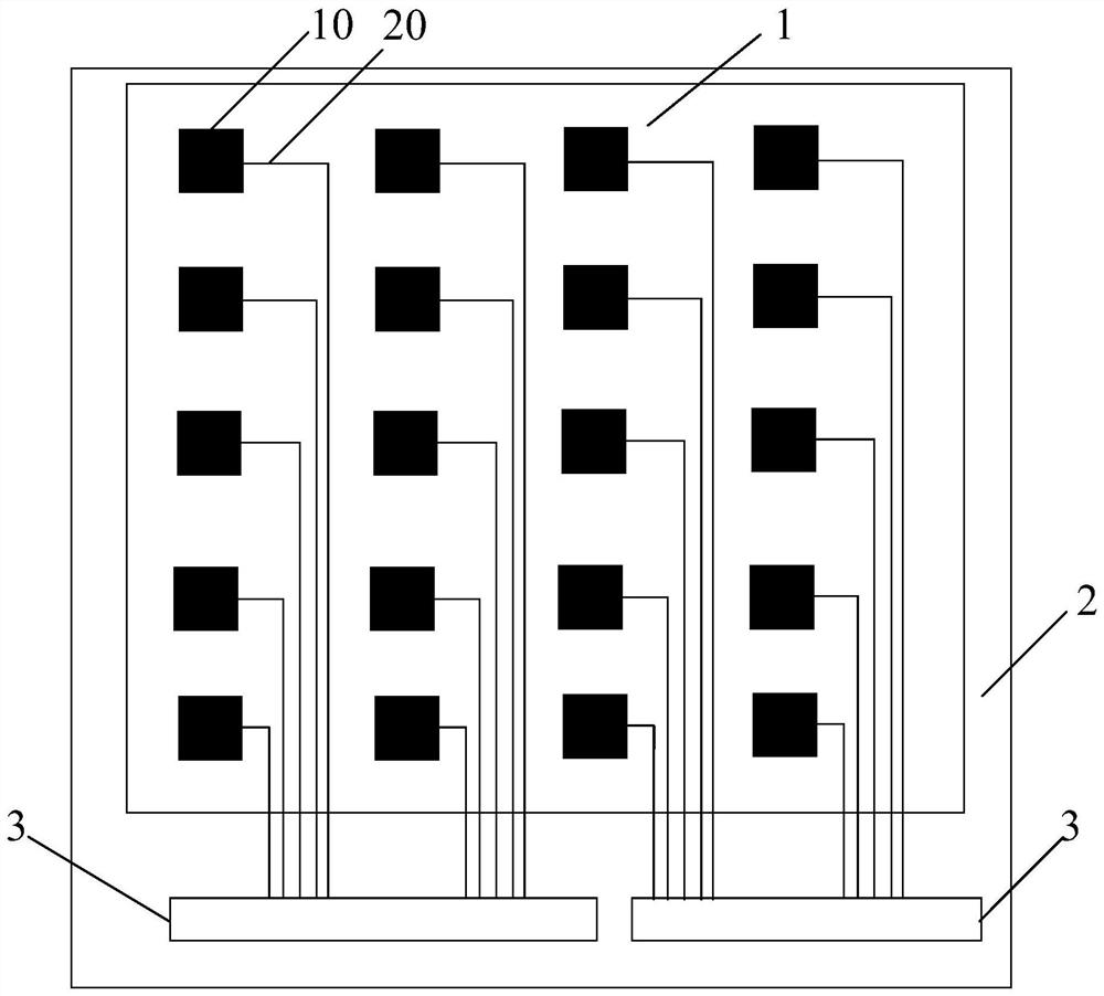
For this self-capacitive touch screen, if the touch electrodes 10 in each column input the same driving signal at the same time, the touch electrodes 10 in adjacent columns will not interfere with each other. However, in order to reduce power consumption and prevent false detection , the touch scanning process generally scans the touch electrodes 10 column by column (or a few columns) to determine the touch point, that is, it only needs to input the driving signal to the column of the touch electrodes 10 being scanned column by column and collect the touch signal, In this way, there is a potential difference between a column of touch electrodes 10 being scanned and two adjacent columns of touch electrodes 10 , so two adjacent columns of touch electrodes 10 will affect a column of touch electrodes 10 being scanned and the touch electrodes connected thereto. Signal lines 20 cause interference, resulting in inaccurate touch monitoring of a row of touch electrodes 10 being scanned, resulting in poor touch performance of the display panel
like figure 1 As shown, if the second row of touch electrodes 10 is being scanned, the touch signal line 20 connected to the second row of touch electrodes 10 inputs a high-frequency drive signal to the second row of touch electrodes 10, and at this time the first row The touch electrodes 10 and the third row of touch electrodes 10 are floating or grounded or connected to other low-frequency driving signals, which will make the touch signal line 20 connected to the first row of touch electrodes 10 and the second row of touch electrodes 10 There is a potential difference between the touch electrodes 10 in the third column and the touch signal lines 20 connected to the touch electrodes 10 in the second column. Therefore, the touch signal lines 20 connected to the touch electrodes 10 in the first column 20 and the third row of touch electrodes 10 will interfere with the second row of touch electrodes 10 and the touch signal lines 20 connected thereto, making the touch performance of the second row of touch electrodes 10 inaccurate
[0004] Therefore, there is an urgent need to propose a new self-capacitive touch panel to solve the problem that when scanning the touch electrodes column by column, the potential of the touch electrodes in the scanning column is different from that of the two adjacent columns. Two columns of touch electrodes and the touch signal lines connected to them interfere with a column of touch electrodes being scanned and the touch signal lines connected to them, resulting in inaccurate touch monitoring of the column of touch electrodes being scanned

Method used


Image

  • Self-capacitance touch panel
  • Self-capacitance touch panel
  • Self-capacitance touch panel

Examples


Embodiment Construction

[0033] The technical solutions in the embodiments of the present application will be clearly and completely described below in conjunction with the drawings in the embodiments of the present application. Apparently, the described embodiments are only some of the embodiments of this application, not all of them. Based on the embodiments in this application, all other embodiments obtained by those skilled in the art without making creative efforts belong to the scope of protection of this application.

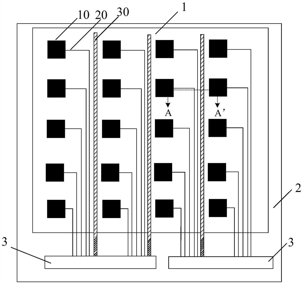
[0034] figure 2 Schematic diagram of the structure of the self-capacitive touch panel provided for the embodiment of the present application, such as figure 2 As shown, the self-capacitive touch panel includes a touch area 1 and a peripheral area 2 surrounding the touch area 1. At least one touch integrated circuit 3 is arranged in the peripheral area 2. Each touch electrode 10 is grounded and connected to the touch integrated circuit 3 through a single touch signal line 20 ....


PUM


Abstract

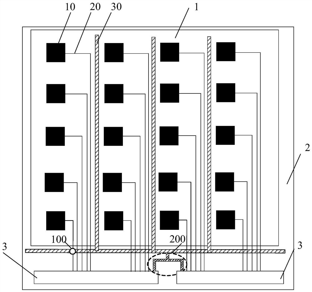
The invention provides a self-capacitance touch panel. Signal shielding lines are arranged between a plurality of touch signal lines connected with each column of touch electrodes and two columns of touch electrodes adjacent to the column of touch electrodes. Interference of two adjacent columns of touch control electrodes and touch control signal lines connected with the two adjacent columns of touch control electrodes on each column of touch control electrodes and the touch control signal lines connected with the two adjacent columns of touch control electrodes is reduced through the signal shielding lines, so that the situation that when the touch control electrodes are scanned column by column, potential difference exists between one column of touch control electrodes which are being scanned and the two adjacent columns of touch control electrodes, as a result, two adjacent columns of touch electrodes and touch signal lines connected with the two adjacent columns of touch electrodes will interfere with a column of touch electrodes which are being scanned and the touch signal lines connected with the two adjacent columns of touch electrodes, touch monitoring of the column of touch electrodes which are being scanned is not accurate enough, and therefore the touch performance of the self-capacitance touch panel is affected can be avoided.

Description

technical field [0001] The present application relates to the field of display technology, in particular to a self-capacitive touch panel. Background technique [0002] Projected capacitive touch screens include self-capacitive touch screens and mutual-capacitive touch screens, in which the horizontal and vertical touch electrode arrays are made of ITO (indium tin oxide) transparent conductive materials on the glass surface, if the horizontal touch electrodes and the vertical touch electrodes respectively form capacitance with the ground, which is self-capacitance. When a finger touches the touch screen, the capacitance of the finger will be superimposed on the self-capacitance, making the self-capacitance larger, so the touch can be determined through the self-capacitance. Control point; if the horizontal touch electrode and the vertical touch electrode intersect, a capacitance will be formed, which is mutual capacitance. When the finger touches the touch screen, the mutual...

Claims


Application Information

Patent Timeline
Patent Type & Authority Applications(China)
IPC IPC(8): G06F3/041G06F3/044
CPCG06F3/0412G06F3/04164G06F3/0445G06F3/0446G06F2203/04103G06F3/0418G06F3/04166G06F3/0443G06F3/041G06F2203/04107
Inventor 方亮
Owner WUHAN CHINA STAR OPTOELECTRONICS TECH CO LTD
Learn More